


4 Pelco Manual C2428M-A (2/01)
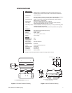
DESCRIPTION
The EU3512-3X is an indoor/outdoor light-duty camera enclosure and light-duty wall mount.
The enclosure includes a sun shroud and 230 VAC heater and defroster. The wall mount has
an adjustable tilt table allowing for mechanical positioning of the enclosure.
Install the EU3512-3X to any wall or vertical surface, capable of supporting up to 20 pounds (9 kg).
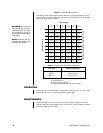
INSTALLATION
INSTALL WALL MOUNT
Perform the following steps to install the mount:
1. Determine the mounting location. Use the flanged end of the mount as a template and
mark the fastener hole positions onto the mounting surface.
– Mounting to a solid surface mark the three fastener holes
– Mounting to a wall stud mark the two center fastener holes
2. Set the mount to the side and prepare the holes for the fasteners.
3. Position the mount over the mounting holes and secure with fasteners.
– Mounting to a solid surface, secure with three .25-inch diameter fasteners
(not supplied)
– Mounting to a wall stud, secure with one .3125-inch fastener and one .25-inch
fastener (not supplied)
If you install the mount outdoors, seal the fastener holes with an appropriate sealant to
prevent water damage. Apply the sealant between the mount and the mounting
surface.
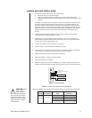
ENCLOSURE INSTALLATION
1. Unlatch and open the lid of the enclosure.
2. Remove the camera sled from the rail of the enclosure.
a. Loosen the screws that hold the camera sled in place.
b. Slide the sled forward so it can be lifted out over the screws.
c. Remove the sled.
d. Remove the parts tied to the sled.
3. If you are wiring the enclosure with cable, remove the glands and nuts from the parts
bag and install them in the bottom of the enclosure. If you are wiring the enclosure
with conduit, do not install the glands.
4. Attach the base of the enclosure to the mount tilt table with the two 1/4-20 x .50-inch
screws (provided).
5. Loosen the cap nut located on the support bracket of the tilt table and adjust the tilt
table to the desired direction. Tighten the cap nut. Loosen the two screws on the tilt
table and adjust it for the desired angle. Tighten the screws.