Pelco Manual C2428M-A (2/01) 5
CAMERA AND LENS INSTALLATION
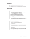
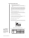
1. To install the camera and lens onto the enclosure sled:
a. Extend the lens to the maximum length.
b. Position the camera and lens so that they do not extend beyond the track.
c. Fasten the camera and lens to the sled with the two, 1/4-20 x .375 Phillips screws
supplied.
The edges of the sled are bent, one side up and the other side down. One side of the
sled has a wide lip and the other side has a narrow lip. In a typical installation, you
mount the camera so that the holes in the wide lip of the sled fit over the sled mount-
ing screws. However, you can elevate the sled if you are installing a camera with a low
optical centerline or a camera with a large diameter lens. To elevate the sled, flip the
sled over so that the holes in the narrow lip of the sled fit over the sled mounting
screws.
2. Install the sled and camera assembly into the enclosure. Slide the sled over the
mounting screws and lightly tighten the screws.
3. Pull the power wires and cables through the glands or conduit into the enclosure.
Refer to Tables A and B to determine the size of the power wire to use. Refer to Table
C for the type of video coaxial cable to use.
4. Connect the cables for power and video to the camera.
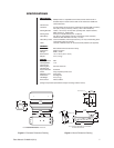
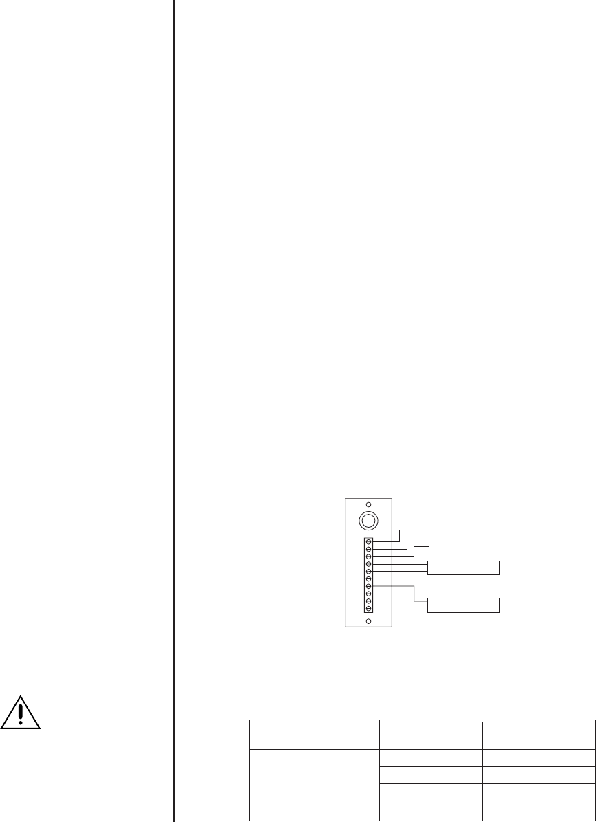
5. Refer to Figure 1 to wire the heater and defroster to power.
6. If the camera lens is adjustable, extend the lens to its maximum length; verify that the
end of the lens is a minimum of .50-inch from the enclosure window.
7. Tighten the screws that secure the sled to the enclosure.
8. Adjust the glands for a tight fit around the cables.
9. Close the enclosure lid, and latch.
10. Adjust the camera focus and iris if necessary. If you need to adjust the focus and iris
manually, open the enclosure lid, adjust the focus and iris, and close the enclosure lid.
Figure 1. Wiring Diagram
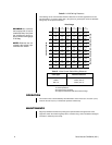
Table A. Heater and Defroster Wiring Distances
The following cable sizes are the minimum recommended for use with the heater and defroster.
Input Power Cable Cable
Voltage Consumption Size Distance
20 AWG (0.5 mm
2
) 20,045 ft (6,109 m)
13 watts 18 AWG (1.0 mm
2
) 31,890 ft (9,720 m)
16 AWG (1.5 mm
2
) 50,612 ft (15,426 m)
14 AWG (2.5 mm
2
) 80,738 ft (24,608 m)
230 VAC
at 50 Hz
CAUTION:
When
using a single
power source for
both camera and accesso-
ries, consider the camera
power consumption when
determining the wire gauge.
Table A does not include
camera power.
1
2
3
4
5
6
7
8
9
10
HEATER
DEFROSTER
INPUT, AC HIGH
INPUT, AC LOW (NEUTRAL)
GROUND