


12 C2652M (1/08)
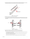
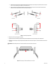
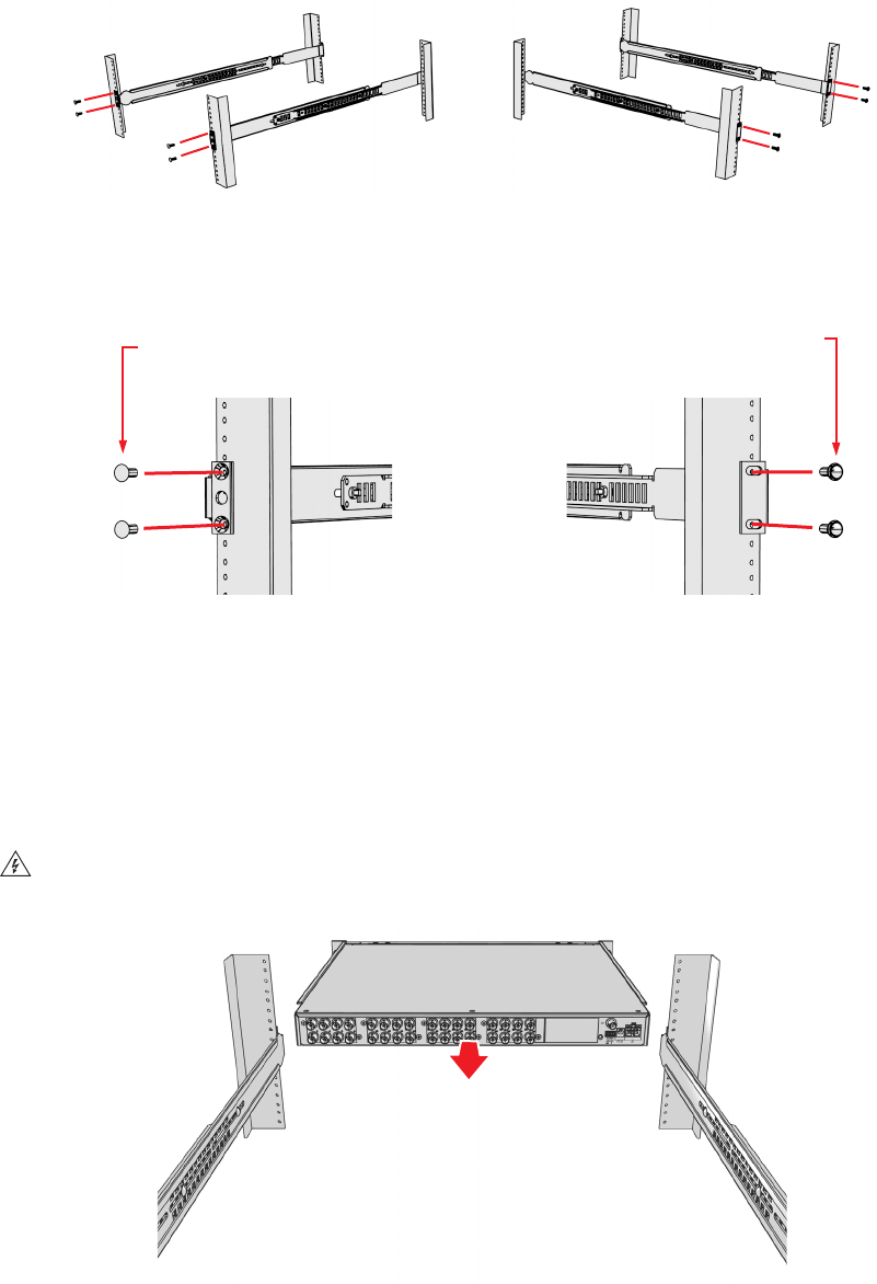
d. Position the ear of the rear-mount rail against the rear exterior of the equipment rack, and align the top and bottom holes in the ear of
the rail with the threaded holes (or cage nuts) in the equipment rack.
e. Using two 10-32 x 0.5-inch Phillips pan head screws, attach the ear of the rail to the rear of the rack. Insert the screws from the
outside of the rack, pointing toward the front of the rack (refer to Figure 11).
Figure 11. Attaching Support Rails
6. Repeat step 5 for the second support rail assembly.
7. Tighten the 8-32 x 0.375-inch Phillips truss head screws that were attached to the front- and rear-mount rails in steps 2 and 3.
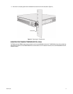
8. Place the unit onto the support rails by sliding the chassis brackets onto the rails (refer to Figure 12). The unit should slide in and out of the
rack easily.
Figure 12. Mounting the Transmitter/Receiver into a Rack
WARNING: When sliding the unit out of the rack, be careful not to let the unit fall out of the rack.
REAR-MOUNT RAIL
FRONT-MOUNT RAIL
(2) SCREWS,
10-32 X 0.5-INCH
PHILLIPS FLAT HEAD
(2) SCREWS,
10-32 X 0.5-INCH
PHILLIPS PAN HEAD
RACK FRONT RACK REAR