6 C2652M (1/08)
FRONT PANEL
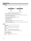
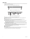
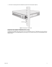
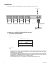
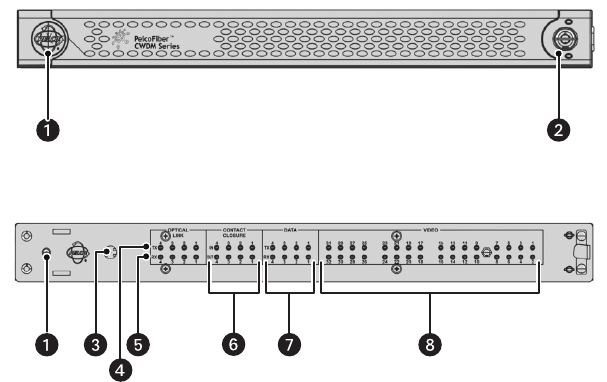
The front panel of the FT8332/FR8332 unit provides a removable bezel. Figure 2 illustrates the front of the unit with the bezel attached. Figure 3
illustrates the front of the unit with the bezel removed.
NOTE: The Contact Closure Activation and Data Activity LEDs shown in Figure 3 are not used.
Figure 2. Front Panel of FT8332/FR8332 Unit with Bezel
Figure 3. Front Panel of FT8332/FR8332 Unit Without Bezel
For troubleshooting information relating to the front-panel LEDs, refer to Troubleshooting on page 15.
ì Power LED: Lights the Pelco badge blue to indicate that power is being applied to the unit.
NOTE: When the bezel is removed from the front panel, the Power LED does not light to indicate that power is being applied to the unit.
î Keylock: Locks/unlocks the front bezel.
ï LED Activation Switch: Lights the front-panel Optical Link and Video Present LEDs as appropriate when the bezel is removed.
NOTE: When the bezel is attached to the front panel, the Optical Link and Video Present LEDs do not light.
ñ TX Optical Link LEDs 1-4: (Applicable to FT8332 transmitter only) Light to indicate laser status. Green indicates that the laser is operating
properly. Flashing red indicates that the laser has shut down.
NOTE: The TX Optical Link LEDs operate independently of one another. TX Optical Link LED 1 indicates the laser status of channels 1-8.
TX Optical Link LED 2 indicates the laser status of channels 9-16. TX Optical Link LED 3 indicates the laser status of channels 17-24. TX Optical
Link LED 4 indicates the laser status of channels 25-32.
ó RX Optical Link LEDs 1-4: (Applicable to FR8332 receiver only) Light to indicate optical signal status. Green indicates that the optical signal is
being received. Red indicates that the optical signal is not being received.
NOTE: The RX Optical Link LEDs operate independently of one another. RX Optical Link LED 1 indicates the optical signal status of channels 1-8.
RX Optical Link LED 2 indicates the optical signal status of channels 9-16. RX Optical Link LED 3 indicates the optical signal status of
channels 17-24. RX Optical Link LED 4 indicates the optical signal status of channels 25-32.
r Contact Closure Activation LEDs: Not used.
s Data Activity LEDs: Not used.
t Video Present LEDs 1-32: Light green on a per-channel basis to indicate that the incoming video signal is present on the channel. Light red on
a per-channel basis to indicate that the incoming video signal is not present on the channel (video loss).


