


2
HOOKING UP THE TELEVISION
A
combination antenna receives normal broadcast chan-
nels (VHF 2–13 and UHF 14–69). Your connection is
easy because there is only one 75Ω (ohm) antenna plug on
the back of your TV, and that’s where the antenna goes.
1
If your antenna has a round cable (75 ohm) on the end,
then you're ready to connect it to the TV.
If your antenna has flat, twin-lead wire (300 ohm), you
first need to attach the antenna wires to the screws on a
300- to 75-ohm adapter.
2
Push the round end of the adapter (or antenna) onto the
75Ω (ohm) plug on the bottom of the TV. If the round end
of the antenna wire is threaded, screw it down finger tight.
ANTENNA TV
COMP
VIDEO
INPUT
Audio in (PC/HD)
HD input
75 Ω
FM ANT
DCin(24V) PCinput(VGA)
L
R
YPbPr
AVI
in
Pr
Pb Y
RL
Audio in
Video in
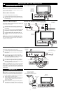
Antenna Connection:
Jack Panel
Bottom of TV
Round 75Ω
Coaxial Cable
from Antenna
Twin
Lead Wire
300 to 75-ohm
Adapter
Outdoor or Indoor Antenna
(Combination VHF/UHF)
The combination antenna receives normal
broadcast channels 2-13 (VHF) and 14-69 (UHF).
COMP
VIDEO
INPUT
Audio in (PC/HD)
HD input
75 Ω
FM ANT
DCin(24V) PCinput(VGA)
L
R
YPbPr
AVI
in
Pr
Pb Y
RL
Audio in
Video in
Y
our Cable TV input into your home may be a single (75 ohm)
cable or use a cable box decoder. In either case the connec-
tion is very simple. Follow the steps below to connect your cable
signal to your new television.
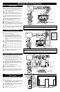
Direct Cable Connections:
This connection will supply Stereo sound to the TV.
1
Connect the open end of the round Cable Company sup-
plied cable to the 75Ω input on the bottom of the TV. Screw
it down finger tight.
Cable Box (w/RF In/Outputs):
This connection will NOT supply Stereo sound to the TV. The sound
from the cable box will be mono.
1
Connect the open end of the round Cable Company sup-
plied cable to
the cable signal IN(put) plug on the back of
the Cable Box.
2
Using a separate round coaxial cable, connect one end to the
OUT(put) (TO TV) plug on the back of the Cable Box.
3
Connect the other end of the round coaxial cable to the
75Ω input on the bottom of the television. Screw it down fin-
ger tight.
NOTE: Be sure to set the OUTPUT CHANNEL SWITCH on the
back of the cable box to CH 3 or 4, then tune the cable box on the
TV to the corresponding channel. Once tuned, change channels at
the cable box, not the television.
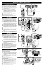
Cable Box (w/Audio/Video Outputs):
This connection will supply Stereo sound to the TV.
1
Connect the open end of the round Cable Company sup-
plied cable to
the cable signal IN(put) plug on the back of
the Cable Box.
2
Using a RCA type Video Cable, connect one end of the
cable to the Video (yellow) (or ANT, your cable box may be
labeled differently) Out jack on the cable box and the other
end to the Video Input on the bottom of the TV.
3
Using a RCA type Audio Left and Right Cable, connect one
end to the left and right Audio Out L & R jacks (red &
white) on the cable box. Connect the other end to the Audio
L& R Input jacks on the bottom of the TV.
NOTE: Use the SOURCE button on the TV remote control to tune to
the AV1 channel for the cable box signal. Once tuned, change chan-
nels at the cable box, not the television. Pressing the SOURCE button
repeatedly will scroll all the AV Input channels, including the present-
ly tuned channel.
CABLE/CABLE BOX TV
COMP
VIDEO
INPUT
Audio in (PC/HD)
HD input
75 Ω
FM ANT
DCin(24V) PCinput(VGA)
L
R
YPbPr
AVI
in
Pr
Pb Y
RL
Audio in
Video in
COMP
VIDEO
INPUT
Audio in (PC/HD)
HD input
75 Ω
FM ANT
DCin(24V) PCinput(VGA)
L
R
YPbPr
AVI
in
Pr
Pb Y
RL
Audio in
Video in
Direct Cable Connection:
Cable Box with RF Inputs and Outputs Connection:
Cable signal
coming from
Cable Company
(Round 75Ω
coaxial cable)
Jack Panel Bottom of TV
Jack Panel Back
of Cable Box
Cable Signal
IN from the
Cable
Company
Round 75Ω
Coaxial Cable
Jack Panel Bottom of TV
Cable Box with Audio/Video Outputs Connection:
Cable Signal IN
from the Cable
Company
Jack Panel Back
of Cable Box with A/V Outputs
Jack Panel Bottom of TV
Audio Cables
L& R (Red, White)
Video Cable (Yellow)
Output Channel Switch