


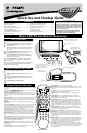

HOOKING UP THE TELEVISION
4
T
he Monitor (Audio/Video) out jacks are great for recording with a
VCR or used to connect an external audio system for better audio.
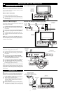
For Audio System Connection:
1
Connect one end of the R(ight) and L(eft) AUDIO (Monitor
Out) jacks located on the right rear of the TV to the R and L
audio input jacks on your sound system. Refer to the AUDIO
OUT control within the Directions for Use for FIXED or VARI-
ABLE settings.
2
Turn the TV and audio system ON. TV sound can be heard
through the audio system
For Second VCR Connection/Recorder:
The following steps allow you to connect a VCR to record the pro-
gram while your watching it.
3
Connect one end of the yellow Video Cable to the Monitor
out VIDEO OUT plug on the left rear of the TV. Connect the
other end to the VIDEO IN plug on the second VCR.
4
Connect one end of the red and white Audio cable from the
Monitor out L and R plugs on the left rear of the TV to the
AUDIO IN plugs on the VCR.
5
Turn the VCR ON, insert a black VHS tape and it’s ready to
record what’s being viewed on the TV screen.
M
ONITOR OUTPUTS
PIP
CC
PROG. LIST
CLOCK
A/CH
TV/VCRSLEEP
SOURCE
FORMAT
AUTO
ACTIVE
AUTO
SOUND
CONTROL
PICTURE
MENU SOUND
SURR.
VOL
CH
MUTE
PC
TV
HD
RADIO
1
23
TV
DVD
ACC
POSITION
COMP
VIDEO
INPUT
Audio in (PC/HD)
HD input
75 Ω
FM ANT
DCin(24V) PCinput(VGA)
L
R
YPbPr
AVI
in
Pr
Pb Y
RL
Audio in
Video in
1
2
4
PC
Audio
Out
VGA/RGB
Out
3
T
his TV can be used as a PC Monitor. Your computer will have
to be equipped with a VGA type video output and VGA cable.
1
Connect one end of the VGA Video cable to the Monitor
(video) output on the computer to the PC Input (VGA) jack
on the bottom of the TV.
2
Although audio connections are not required, the TV can
reproduce the computers audio out by an AUDIO
ADAPTER to the Audio output jack on the computer (if
available) while connecting the other ends of the Audio
cables to the Audio In left and right (PC/HD) Input Jacks
on the bottom of the TV.
3
Turn the TV and the Computer ON.
4
Press the PC Mode button to set the TV into the HD
Mode and tune to the computer’s signal.
Note: Please contact your dealer or Philips at 800-531-0039 for
information about purchasing the needed cables.
PC (M
ONITOR) INPUTS
AUDIO
ADAPTER
VGA CABLE
BOTTOM OF TV
PC with VIDEO VGA OUT
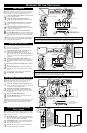
T
here are Audio/Video Input Jacks located on both sides of the TV
located under removable panels. These jack allow for extra acces-
sory device connections for items such as cameras or gaming stations.
1
Connect the VIDEO (yellow) cable to the VIDEO AV2 in
jack on the left rear of the TV. Connect the other end of the
VIDEO (yellow) cable to the VIDEO OUT jack on the back of
the accessory device being used. Note: An S-Video cable can
be used in place of the yellow Video cable if your device is
equiped with an S-Video Output. S-Video provides better video
playback.
2
Connect the AUDIO (red and white) cables to the AUDIO
(left and right) AV2 in jacks on the left rear of the TV. Connect
the other ends of the AUDIO (red and white) cables to the
AUDIO (left and right) OUT jacks on the rear of the accessory
device being used.
3
Turn the accessory device and the TV ON.
4
Press the SOURCE button on the remote control repeatedly
to select the AV2 channel for the accessory device. AV2 will
appear in the upper left corner on the TV screen when tuned
properly.
5
With the accessory device ON, press the PLAY button to acti-
vate the playback on the television.
AV2 INPUTS
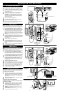
M
uch like the AV2 jacks, the AV3 jacks allow for extra accessory
device connections for items such as cameras or gaming stations.
The AV3 Input Jacks are located on the right rear of the TV.
1
Connect the VIDEO (yellow) cable to the VIDEO AV3 in jack
on the right rear of the TV. Connect the other end of the
VIDEO (yellow) cable to the VIDEO OUT jack on the back of
the accessory device being used. Note: An S-Video cable can be
used in place of the yellow Video cable if your device is equiped
with an S-Video Output. S-Video provides better video playback.
2
Connect the AUDIO (red and white) cables to the AUDIO
(left and right) AV2 in jacks on the right rear of the TV. Connect
the other ends of the AUDIO (red and white) cables to the
AUDIO (left and right) OUT jacks on the rear of the accessory
device being used.
3
Turn the accessory device and the TV ON.
4
Press the SOURCE button on the remote control repeatedly to
select the AV3 channel for the accessory device. AV3 will appear
in the upper left corner on the TV screen when tuned properly.
5
With the accessory device ON, press the PLAY button to acti-
vate the accessory device (DVD, VCR, CAMERA, etc.) and
view the playback on the television.
AV3 INPUTS
S-VIDEO
VIDEOAUDIO
RIGHT LEFT
5
3
2
Data
Sub
woofer
out
VIDEO
VIDEO
out
in
L
L
R
R
Monitor
out
AV2
in
S-VIDEO
1
PIP
CC
PROG. LIST
CLOCK
A/CH
TV/VCRSLEEP
SOURCE
FORMAT
AUTO
ACTIVE
AUTO
SOUND
CONTROL
PICTURE
MENU SOUND
SURR.
VOL
CH
MUTE
PC
TV
HD
RADIO
1
23
456
789
0
STATUS/EXIT
SURF
TV
DVD
ACC
POSITION
4
AUDIO CABLES
(Left and Right)
VIDEO CABLE
ACCESSORY DEVICE
JACK PANEL
ACCESSORY DEVICE
(Camera., DVD, VCR, etc.)
AN S-VIDEO CABLE CAN BE
USED IN PLACE OF THE
YELLOW VIDEO CABLE IF
DESIRED.
S-VIDEO
VIDEO
AUDIO
L
R
S-VIDEO
VIDEOAUDIO
RIGHT LEFT
5
3
2
1
PIP
CC
PROG. LIST
CLOCK
A/CH
TV/VCRSLEEP
SOURCE
FORMAT
AUTO
ACTIVE
AUTO
SOUND
CONTROL
PICTURE
MENU SOUND
SURR.
VOL
CH
MUTE
PC
TV
HD
RADIO
1
23
456
789
0
STATUS/EXIT
SURF
TV
DVD
ACC
POSITION
4
Data
Sub
woofer
out
VIDEO
VIDEO
out
in
L
L
R
R
Monitor
out
AV2
in
S-VIDEO
AUX/TV INPUT
PHONO INPUT
R
L
1
2
ACCESSORY DEVICE
(Camera., DVD, VCR, etc.)
JACK PANEL
BACK RIGHT OF TV
AUDIO
CABLES
(Left and
Right)
VIDEO CABLE
ACCESSORY DEVICE
JACK PANEL
AN S-VIDEO CABLE CAN BE
USED IN PLACE OF THE
YELLOW VIDEO CABLE IF
DESIRED.
Data
Sub
woofer
out
VIDEO
VIDEO
out
in
L
L
R
R
Monitor
out
AV2
in
S-VIDEO
ANTENNA
OUT
ANTENNA
IN
VIDEO
AUDIO
IN
IN
OUT OUT
RL
3
4
5
Audio System
Connection:
Second VCR
Connection/Recorder:
AUDIO CABLES
(Red & White)
AUDIO SYSTEM
with AUDIO INPUTS
AV OUT
AUDIO L(eft) and R(ight)
JACK PANEL
Located on the back left of the
TV
AUDIO CABLES (Red & White)
Monitor OUT
VIDEO &AUDIO
L(eft) and R(ight)
SECOND VCR
VIDEO CABLE
(Yellow)
JACK PANEL
BACK LEFT OF TV