


HOOKING UP THE TELEVISION
3
COMP
VIDEO
INPUT
Audio in (PC/HD)
HD input
75 Ω
FM ANT
DCin(24V) PCinput(VGA)
L
R
YPbPr
AVI
in
Pr
Pb Y
RL
Audio in
Video in
PIP
CC
PROG. LIST
CLOCK
A/CH
TV/VCRSLEEP
SOURCE
FORMAT
AUTO
ACTIVE
AUTO
SOUND
CONTROL
PICTURE
MENU SOUND
SURR.
VOL
CH
MUTE
PC
TV
HD
RADIO
1
23
456
789
STATUS/EXIT
SURF
TV
DVD
ACC
POSITION
2
1
3
4
IN FROM ANT SATELLITE IN
OUT TO TV
CH 3
CH 4
DIGITAL
AUDIO OUT
VCR
CONTROL
S-VIDEO
VIDEO
in 2
R
L
AUDIO
RF
REMOTEPHONE JACK
Coaxial Cable
Lead-in
from
Satellite
Dish Antenna
Rear of HD Receiver
(Illustration is for reference only.
Your HD Receiver's jack panel will
look and be labelled different.)
VIDEO
in 1
R
L
AUDIO
PB
PR
Y
Coaxial Cable Lead-in
from Cable Outlet,
Cable Converter Box,
or VHF/UHF Antenna
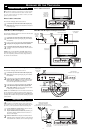
HD 1
I
f your using a High Definition receiver that can transmit high
definition programming, the TV can except those signals
through the HD Inputs located on the bottom of the TV.
1
Connect the Component (Y, Pb, Pr) Video OUT jacks
from the HD Receiver (or similar device) to the HD (Y, Pb,
Pr) input jacks on the bottom of the TV.
2
Connect the red and white AUDIO CABLES to the
Audio (left and right) output jacks on the rear of the HD
Receiver to the Audio In (PC/HD) Input Jacks on the bot-
tom of the TV.
3
Turn the TV and the HD Receiver ON.
4
Press the HD Mode button to set the TV into the HD
Mode and tune to the HD signal.
Note: The Audio/Video cables needed for this connection are not
supplied with your TV. Please contact your dealer or Philips at
800-531-0039 for information about purchasing the needed
cables.
HD (H
IGH
DEFINITION
) INPUTS
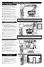
T
he audio/video input jacks on the bottom panel of the TV are
for direct picture and sound connections between the TV and
a VCR (or similar device) that has audio/video output jacks.
1
Connect the VIDEO (yellow) cable to the VIDEO AV1 in
jack on the bottom of the TV.
2
Connect the AUDIO (red and white) cables to the
AUDIO (left and right) AV1 in jacks on the bottom of the
TV.
3
Connect the VIDEO (yellow) cable to the VIDEO OUT
jack on the back of the VCR or accessory device being
used.
4
Connect the AUDIO (red and white) cables to the
AUDIO (left and right) OUT jacks on the rear of the VCR
or accessory device being used.
5
Turn the VCR or accessory device and the TV ON.
6
Press the SOURCE button on the remote control to select
the AV1 channel for the accessory device. AV1 will appear
in the upper left corner on the TV screen when tuned prop-
erly.
7
With the VCR (or accessory device) ON and a prerecorded
tape (CD, DVD, etc.) inserted, press the PLAY button to
view the tape on the television.
AV1 I
NPUTS
COMP
VIDEO
INPUT
Audio in (PC/HD)
HD input
75 Ω
FM ANT
DCin(24V) PCinput(VGA)
L
R
YPbPr
AVI
in
Pr
Pb Y
RL
Audio in
Video in
PIP
CC
PROG. LIST
CLOCK
A/CH
TV/VCRSLEEP
SOURCE
FORMAT
AUTO
ACTIVE
AUTO
SOUND CONTROL
PICTURE
MENU SOUND
SURR.
VOL
CH
MUTE
PC
TV
HD
RADIO
1
23
456
789
0
STATUS/EXIT
SURF
TV
DVD
ACC
POSITION
Note: The Audio/Video cables needed for this connection are not supplied with your TV. Please contact
your dealer or Philips at 800-531-0039 for information about purchasing the needed cables.
H
ELPFUL HINT
AUDIO IN
(RED/WHITE)
BOTTOM OF TV
VCR (or accessory device)
(EQUIPPED WITH VIDEO AND
AUDIO OUTPUT JACKS)
BACK OF VCR
(or Accessory device)
VIDEO IN (YELLOW)
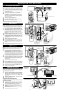
C
omponent Video inputs provide the highest possible color and
picture resolution in the playback of digital signal source
material, such as with DVD players.
1
Connect the Component (Y, Pb, Pr) Video OUT jacks
from the DVD player (or similar device) to the
COMP(onent) VIDEO Input (Y green, Pb blue, Pr red)
jacks on the bottom of the TV. When using the Component
Video Inputs, it is best not to connect a signal to the AV1 in
Video Jack.
2
Connect the red and white AUDIO CABLES to the
Audio (left and right) output jacks on the rear of the acces-
sory device to the Audio (L and R) AV1 in Input Jacks on
the TV.
3
Turn the TV and the DVD (or digital accessory device)
ON.
4
Press the SOURCE button to scroll the available chan-
nels until CVI appears in the upper left corner of the TV
screen.
5
Insert a DVD disc into the DVD player and press the
PLAY
ᮣ button on the DVD Player.
COMPONENT (CVI) INPUTS
COMP
VIDEO
INPUT
Audio in (PC/HD)
HD input
75 Ω
FM ANT
DCin(24V) PCinput(VGA)
L
R
YPbPr
AVI
in
Pr
Pb Y
RL
Audio in
Video in
PIP
CC
PROG. LIST
CLOCK
A/CH
TV/VCRSLEEP
SOURCE
FORMAT
AUTO
ACTIVE
AUTO
SOUND
CONTROL
PICTURE
MENU SOUND
SURR.
VOL
CH
MUTE
PC
TV
HD
RADIO
1
23
456
789
0
STATUS/EXIT
SURF
TV
DVD
ACC
POSITION
S-VIDEO
OUT
OUT
OUT
L
R
AUDIO
VIDEO
COMP VIDEO
Pb
Pr
2
1
3
5
4
Y
TUNE TO AV1 CHANNEL
The description for the component video connectors may differ depending on the DVD player or accessory
digital source equipment used (for example, Y, Pb, Pr; Y, B-Y, R-Y; Y, Cr, Cb). Refer to your DVD or dig-
ital accessory owner’s manual for definitions and connection details.
HELPFUL HINT
AUDIO CABLES
(RED/WHITE)
COMPONENT
VIDEO CABLES
(Green, Blue, Red)
BOTTOM OF TV
ACCESSORY DEVICE
EQUIPPED WITH COMPO-
NENT VIDEO OUTPUTS.
The CVI connection
will be dominate over
the AV1 in Video Input.
When a Component
Video Device is con-
nected as described, it is
best not to have a video
signal connected to the
AV 1 in Video Input
jack.
AUDIO
CABLES
COMPONENT
VIDEO CABLES
(Green, Blue, Red)
BOTTOM OF TV
HD RECEIVER
EQUIPPED WITH COMPONENT
VIDEO OUTPUTS.
T
he left side Jack Panel contains three jacks that can be used
for your convenience. They include a Headphone Jack, a Sub-
Woofer Jack, and a Data Jack.
1
HEAD PHONE JACK - Used for headphone listening in
any of the available modes. When headphones are connect-
ed to this jack the TV speakers will be muted.
2
SUB-WOOFER JACK - An external Sub-woofer speaker
can be connected to the TV at this jack. This would pro-
vide for a deeper bass sound.
3
DATA JACK - This jack is used in service applications
and should not be used by the customer.
HEADPHONE/SUB-WOOFER
/DATA JACKS
Data
Sub
woofer
out
VIDEO
VIDEO
out
in
L
L
R
R
Monitor
out
AV2
in
S-VIDEO
2
3
1
TV VIEWED FROM THE BACK
JACKS LOCATED
ON THE LEFT
REAR OF THE TV