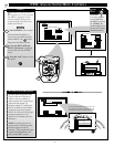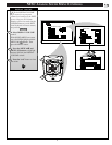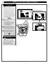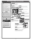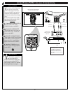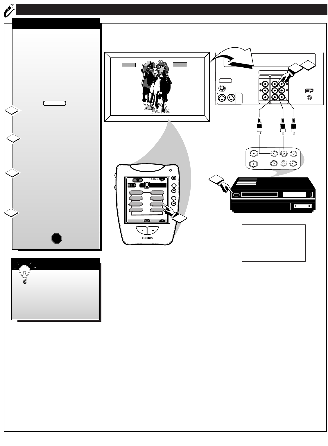
AUDIO/VIDEO NTSC ANALOG CONNECTIONS
ANALOG
TV ANT/CABLE
AUX 1 AUX 2
S-VIDEO
ANALOG
AUDIO OUT
AUDIO INPUT
AUX 1 AUX 2
VIDEO OUT
VIDEO INPUT
L
R
L
R
IR BLASTER
TV
NTSCNTSC
++
++
mute
volume
channel
ANTENNA
OUT
IN
OUT
IN
AUDIO
R
L
VIDEO
IN
OUT
1
2
AUX 1AUX 1
analog TV
power
TV
Analog
DTV1/4
sleep
alt audio
status
DTV
ext input
dtv freeze
3
4
AUX1/2 INPUTS
REAR OF DPTV
VIDEO IN
(YELLOW)
AUDIO IN
(RED/WHITE)
If you have a single (monaural)
Audio Output VCR, "Y" connectors
are available to complete your
connection. Contact your dealer, or
our Parts Information Center (1-
800-292-6066) to order any optional
accessories.
VCR
PICTURE AND SOUND FROM
PLAYBACK OF VCR TAPE
SMART HELP
AUDIO/VIDEO
OUTPUT JACKS
ON VCR
24
T
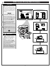
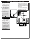
he Analog Audio/Video Input
jacks are for direct NTSC
picture and sound connections
between the DPTV and auxiliary
equipment (VCR, DVD Player,
etc.) that has Audio/Video Output
jacks.
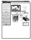
To view the playback of a VCR
tape by using the Analog AUX1
Audio/Video Input jacks:
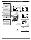
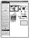
Connect the VIDEO OUT jack
from the VCR to the AUX 1
VIDEO IN jack on the DPTV.
Connect the AUDIO OUT
jacks R(ight) and L(eft) from the
VCR to the AUX 1 AUDIO IN
jacks on the DPTV.
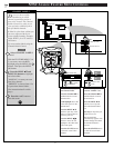
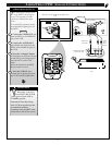
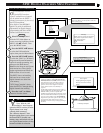
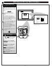
Press the “ext input” button
on the Pronto (or the Source button
on the DPTV’s local keyboard) to
select the AUX 1 Audio/Video
Inputs on the rear of the DPTV.
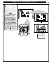
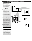
Turn the VCR ON and press
PLAY to view the tape playback
on the DPTV.
1
2
3
4
STOP
BEGIN
Remember, connections
and use of the DPTV's
AUX 2 Audio/Video Input jacks
are the same as for the AUX 1
jacks (except "AUX 2" is selected
as the Input Source in step 3).


