11
C
ONNECTING TO YOUR EXISTING EQUIPMENT (CONT’D)
Unplug all equipment from the AC outlet before making connections.
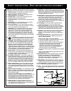
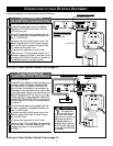
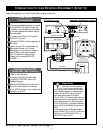
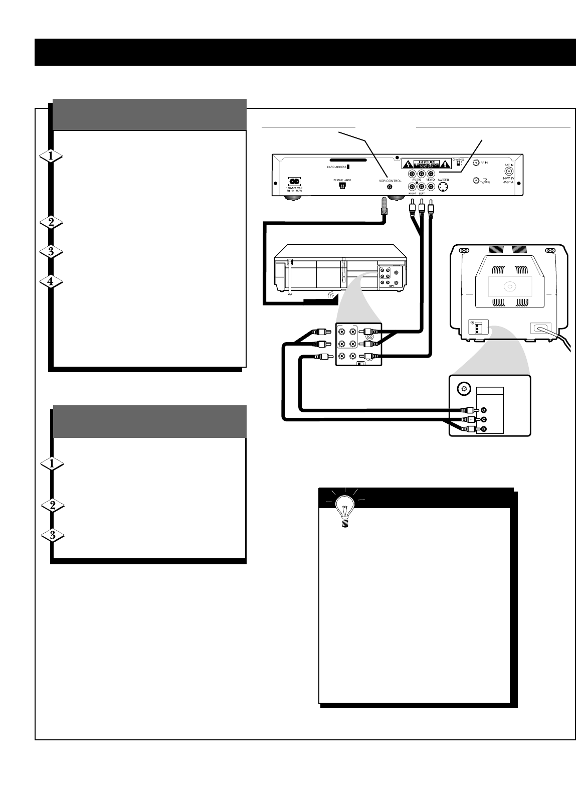
Refer to the illustration at right:
Connect the Satellite Receiver A/V jacks
to the VCR’s A/V IN jacks. Connect the
red cable to the red jacks, the white cable
to the white jacks, and the yellow cable to
the yellow jacks.
Connect the VCR’s A/V OUT jacks to
the TV’s A/V IN jacks.
Connect TV,VCR or other equipment to
AC outlet.
Switch on your TV first and select the
appropriate channel or A/V mode
depending on the connection chosen in
step 2. Refer to the user manuals for
your TV and VCR to select proper
channel or A/V mode (AUX/VCR,
S-VIDEO, …).
If you have a
TV and a VCR
Next, go to Inserting Your Access Card on page 12.
R
L
Video cable
Audio
cables
VHF/
U
HF
A
U
DI
O
VIDE
O
IN
R
VHF/
U
HF
A
U
DI
O
VIDE
O
IN
Rear of TV
CH3 CH4
OUT
IN
ANT
AUDIO
R
L
VIDEO
OUT
IN
INOUT
CH3 CH4
OUT
IN
ANT
AUDIO
R
L
VIDEO
OUT
IN
INOUT
L
RL
IN
L
RL
IN
L
R
L
Rear of VCR
Video cable
Audio cables
R
L
VCR controller cable
Smart Help
• If the audio and video jacks on
your TV are not color-coded, make
sure you connect the audio/video out jacks
on the Satellite Receiver to the audio/video
in jacks on the TV. Connect right jacks to
right jacks, and left jacks to left jacks.
• If your VCR or TV does not have audio and
video jacks, use RF coaxial cables for connec-
tions instead. Connect the RF coaxial cable
to the TV/VCR jack on the Satellite Receiver
and to the RF or ANTENNA IN jack on the
VCR.
Then, connect a second RF coaxial cable to
the ANTENNA OUT or RF OUT jack of the
VCR and to the ANTENNA IN, RF in, or
UHF/VHF IN jack of the TV.
VCR contr
oller output
(DSX3575 only)
Secondar
y Audio/Video Outputs
(DSX5353 and DSX5375 only)
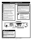
Refer to the illustration:
Connect the VCR Controller cable
to the VCR CONTROL jack on the
Satellite Receiver.
Place the VCR Controller under and in
front of the VCR close to the sensor.
Your VCR Controller is now ready to be
set up for your VCR
Connecting the VCR
Controller
(DSX 5375R only)


