


Alignments
EN 61L06.1E 8.
2. EWW (East-West Width): This sets the (overall) horizontal
size of the picture on the screen. Range from 0 to +63.
3. EWP (East-West Parabola): Align for the vertical lines of
the test picture to be straight lines. Range from 0 to +63.
4. HB (Horizontal Bow): Align the EW parabola to be
symmetrical, range from 0 to +63.
5. HP (Horizontal Parallel): Align for straight vertical lines on
the picture sides, range from 0 to +63.
6. UCP (Upper Corner Parabola): Align for the vertical lines in
the upper corners of the screen to be straight. Range from
0 to +63.
7. LCP (Lower Corner Parabola): Align for the vertical lines in
the lower corners of the screen to be straight. Range from
0 to +63.
8. EWT (East-West Trapezium): Align for equal length of the
horizontal lines in the upper and lower parts of the screen.
Range from 0 to +63.
Now, select “Double Lines” mode, and again align the following
vertical screen geometry setting:
1. VS (Vertical Slope); First activate menu item SBL (Service
Blanking = ON), so the lower part of the test picture is no
longer visible. Then adjust the Vertical Slope. Align for the
horizontal line in the middle of the test picture to line up with
the boundery between the (still visible) upper part of the
screen and the (invisible) lower part of the screen. Range
from 0 to +63. After this, switch the SBL to OFF again.
8.3.3 White Tone
In the WHITE TONE sub menu, the colour values for the
different colour temperatures can be changed.
The colour temperature mode (NORMAL, DELTA COOL,
DELTA WARM) can be selected per colour (R, G, and B) with
the RIGHT/LEFT cursor keys. The mode or value can be
changed with the UP/DOWN cursor keys.
First, the values for the NORMAL colour temperature must be
selected. Then the offset values for the DELTA COOL and
DELTA WARM mode can be selected. Note that the alignment
values are non-linear.
Alignment
Normally, no adjustments are needed.
If the white tone alignment values used in CSM of the the TV
set do not give the required result, use the following alignment
method:
1. Set the external pattern generator to a 100% white pattern,
and connect its RF output to the aerial input of the TV. Set
the amplitude to at least 1 mV
RMS
(60 dBuV) and the
frequency to 475.25 MHz. Use system PAL B/G if possible,
otherwise match the system of your generator with the
received signal in the set.
2. Set "Smart Picture" to "Natural".
3. Set "Dynamic NR" to "off".
4. Put the set in the SAM mode.
5. Select via the WHITE TONE menu, the PATTERN sub-
menu.
6. Set PATTERN to "on".
7. Set NORMAL GREEN to "0".
8. Measure with the colour analyser (Minolta CA100 Colour
Analyser or equivalent), calibrated with the spectra, on the
centre of the screen.
9. Adjust with the cursor left/right command the Red and Blue
register for the right xy-coordinates (see the table below).
10. Repeat the white tone adjustment also for the colour
temperatures COOL and WARM.
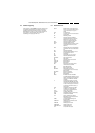
Table 8-1 White tone alignment (with colour analyser)
8.3.4 Sound
No adjustments needed. Use the given default values:
•AF-M = 250
• A2T = 400
•AT = 2
8.3.5 Smart Settings
No adjustments needed.
8.4 Option Settings
8.4.1 Introduction
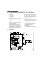
The microprocessor communicates with a large number of I
2
C
ICs in the set. To ensure good communication and to make
digital diagnosis possible, the microprocessor has to know
which ICs to address. The presence / absence of these specific
ICs (or functions) is made known by the option codes.
Notes:
• After changing the option(s), save them with the STORE
command.
• All changes are disregarded when the OPTIONS submenu
is left without using the STORE command.
• The new options setting is only active after the TV is
switched "off" and "on" again with the Mains switch (the
EAROM is then read again).
8.4.2 Changing Options
Options are used to control the presence / absence of certain
features and hardware. There are two ways to change the
option settings. All changes in the option settings are saved by
selecting STORE and pressing the CURSOR RIGHT key.
Some changes will only take affect after the set has been
switched OFF and ON with the mains switch (cold start).
Changing Multiple Options by Changing Option Byte
Values
Option Bytes (OB) makes it possible to set all options very fast.
An option byte represents a number of different options. All
options are controlled via option bytes (OB1 to OB13; each
“OB” number represents 16 bits; bit numbers that are not used
are omitted in the second column). Select an Option Byte you
want to change with the CURSOR UP/DOWN keys, and key in
the new value. See the table for more details. An explanation
per option is listed in paragraph "Option Bit Definition".
Changing a Single Option
It is also possible to change an option one at a time. Therefore,
select the option with the CURSOR UP/DOWN keys and
change its setting with the LEFT/RIGHT keys.
White D mode Temperature DUV x y
Normal 13100 K +-0.004 264 +/- 4 279 +/- 4
Cool 18300 K +-0.005 256 +/- 5 264 +/- 5
Warm 6500 K +-0.005 314 +/- 5 324 +/- 5