


8
PIP ON/OFF
213
546
879
0
TV
SWAP PIP CH
DN
UP
ACTIVE
CONTROL
FREEZE
SOUND
MUTE
SURF
A/CH
POWER
PICTURE
STATUS/
EXIT
SURF
ITR/
RECORD
HOME
VIDEO
HOME
MOVIES
PERSONAL
SLEEP
REC •
VCR
ACC
MENU/
SELECT
VOL
CH
TV/VCR
FORMAT
SAP
PROG.LISTDOLBY VAV
5
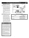
AV1
VIDEO
S-VIDEO
L
Pb
Pr
VIDEO
S-VIDEO
L
AUDIO
L
R
AUDIO
L
R
G/Y
R/Pr
B/Pb
V
H
SYNC
L
R
AUDIO
L
R
AUDIO
HD INPUT-AV 4
HD INPUT-AV 5
INPUT-AV 2 SUBWOOFEROUTPUTINPUT-AV 1
Y
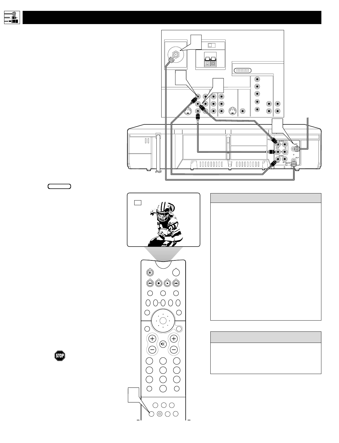
Rear of TV
AMP SWITCH
CENTER CHANNEL AMP INPUT
ANTENNA IN 75Ω
EXT INT
+
_
DVI
Coaxial Cable
Lead-in from
Cable TV Company
or VHF/UHF Antenna
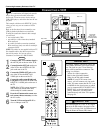
* (Example: Philips VCR
model VR674CAT)
2
Rear of VCR*
3
4
1
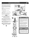
T
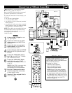
he TV’s audio/video (AV) input jacks provide
for direct picture and sound connections
between the TV and accessory devices such as
VCRs, DVD players, and others that have AV out-
put jacks.
This example, which uses the INPUT-AV 1 jacks,
shows you one way you can connect a VCR to
your TV.
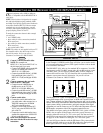
Refer to the directions-for-use manual for your
VCR for further information on connections.
To make the connections shown in this example,
you will need:
• one coaxial cable (75Ω)
• one cable for a video connection (standard
RCA connector)
• two cables for audio connections (standard
RCA connectors) (only one cable is needed for
a nonstereo VCR).
NOTE: The cables are not supplied with your TV.
You should be able to buy them at most stores
that sell electronics. Or you can call our
Customer Care Center at 1-800-531-0039.
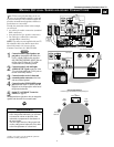
1
Connect a cable TV or antenna signal to
the ANT IN jack on the rear of the VCR.
2
Connect from the OUT jack on the rear
of the VCR to the
ANTENNA IN 75Ω
jack on the rear of the TV.
3
Connect the VIDEO OUT jack on the
rear of the VCR to the INPUT AV1
VIDEO jack on the rear of the TV.
4
Connect the audio output R(ight) and
L(eft) jacks on the rear of the VCR to the
INPUT-AV 1 AUDIO jacks on the rear of
the TV.
NOTE: If the VCR is a mono (nonstereo)
unit, connect only the left audio cable,
which usually has a white connector.
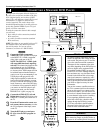
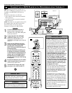
5
Press the AV button on the remote con-
trol as many times as necessary to select
the AV1 source.
6
Turn the VCR on and press PLAY to
view a videotape on the TV.
Connecting Accessory Devices to Your TV
CONNECTING A VCR
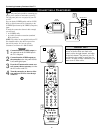
BEGIN
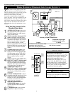
To simplify making connections, audio and
video cables often have color-code connec-
tors. The jacks on your TV are likewise
color coded to match the connectors. The
coding is as follows:
• Yellow for video (composite)
• Red for the right audio channel
• White for the left audio channel
NOTE: If your VCR is mono (non-
stereo), you will connect only one audio
cable. You must ensure that the TV is set
to MONO for the signal source to which
you’ve connected the VCR (
INPUT-AV
1,
INPUT-AV2, or the side panel inputs
[AV3]). Otherwise, you will receive
sound from only one of the TV’s speakers.
See page 38.
HELPFUL
HINT
You can display the AV1, AV2, or AV3 signal
sources in the PIP window. See page 8 of the
Quick Use and Setup Guide for information on
using the Picture-in-Picture (PIP) feature.
cc
C
HECK IT OUT