


23
75 ⍀
VIDEO
L/
Mono
AUDIO
R
Monitor out
AV1 in
S-VIDEO
ANTENNA
OUT
ANTENNA
IN
VIDEO
AUDIO
IN
IN
OUTOUT
LR
S-VHS
75 ⍀
VIDEO
L/
Mono
AUDIO
R
Monitor out
AV1 in
S-VIDEO
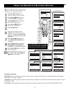
POWER
SLEEP
A/CH STATUS/EXIT CC CLOCK
RECORD
TV
VCR
ACC
SMART
SMARTSMART
SOUND
PICTURE
MENU SURF
VOL
CH
MUTE
1
23
4
5
6
7
89
0
TV/VCR
1
2
3
4
5
6
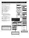
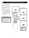
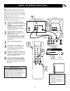
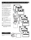
USING THE S-VIDEO INPUT JACK
L
et's
Look
Inside!
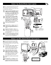
AUDIO IN
(RED/WHITE)
BACK OF VCR
WITH
S-VHS (S-Video) JACKS
S-VIDEO
CABLE
BACK OF TV
Note: SVHS will appear as a
valid channel option only if an
SVHS device is connected to the
S-Video Input Jack.
If the device is connected to
AV1 Video In, the channel will
appear as AV1.
SVHS
T
he S(uper)-Video connection on the rear
of the TV provides better picture detail
and clarity from accessory sources such as a
DBS (digital broadcast satellite), DVD Player
(digital video discs), video games, and S-VHS
VCR (video cassette recorder).
NOTE: The accessory device must have an
S-VIDEO OUT jack in order for you to com-
plete the connection on this page.
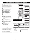
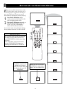
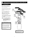
1
Connect one end of an S-VIDEO
cable to the S-VIDEO jack on the back
of the TV.
Connect one end of the AUDIO (red
and white) cables to the AV1 In
AUDIO L and R (left and right) jacks
on the rear of the TV.
2
Connect the other end of the S-
VIDEO cable to the S-VHS (S-Video)
OUT jack on the VCR.
Connect the other ends of the AUDIO
(red and white) cables to the AUDIO
(left and right) OUT jacks on the rear
of the VCR.
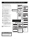
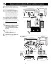
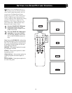
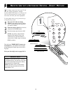
3
Turn on the VCR and the TV.
4
Press the CH + or – buttons on the
TV’s remote to scroll the channels
until SVHS appears in the upper left
corner of the TV screen.
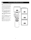
5
Slide the TV/VCR/ACC switch to the
VCR position. Make sure you have set
the TV’s remote to operate your VCR.
Details are on pages 28-33.
6
Now you are ready to place a video-
tape in the VCR and press the ᮣ but-
ton
. (Either press PLAY on the VCR or
ᮣ
on the TV’s remote if it is set to work
the VCR.)
The S-VIDEO and VIDEO AV1 inputs
work in parallel. The S-VIDEO input is
dominant when in use. If separate video sig-
nals are connected to the S-VIDEO and
VIDEO AV1 inputs, the signal at the
VIDEO AV1 input will not be usable.
H
ELPFUL HINT