


8
En
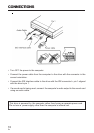
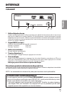
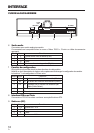
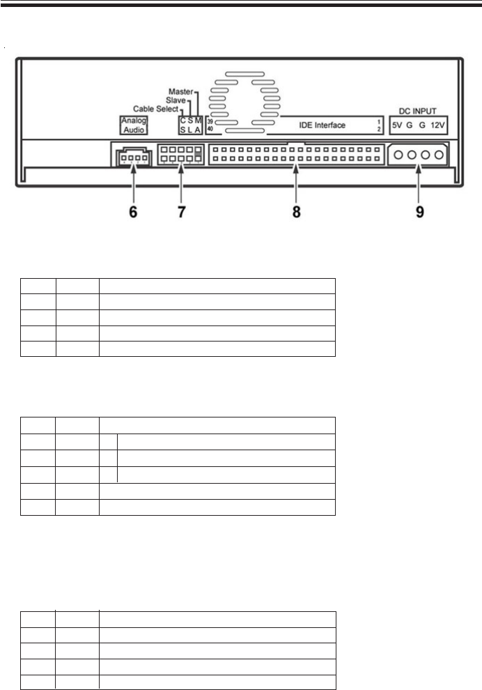
INTERFACE
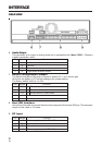
REAR VIEW
Pin Name Function
1 L Left channel audio output
2 G Ground
3 G Ground
4 R Right channel audio output
Pin Name Function
1 MA on The drive is the master device
2 SL on The drive is the slave device
3 CS on Set the drive to Cable Select
4 Reserved
5 Reserved
6 Audio Output
This connector is for output of analog audio and is compatible with Molex 70553. Choose a
suitable connection cable.
Pin Name Function
1 +12 Power supply input for DC +12 V
2 G Ground
3 G Ground
4 +5 Power supply input for DC +5 V
7 Device Configuration Jumper
The Switch changes to ON when a jumper is added (Pin 1 is on lower-right).
Verify that the power is OFF before changing the jumper setting.
The factory default forPin # 1 is ON.
8 Host IDE Interface
Use a 40-pin flat cable to connect the drive to the computer's Enhanced-IDE port. The maximum
length for this cable is 18 inches.
9 DC Input