


IC-485S/IC-485SI
OTHERS
4 OTHERS
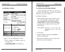
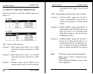
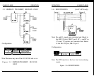
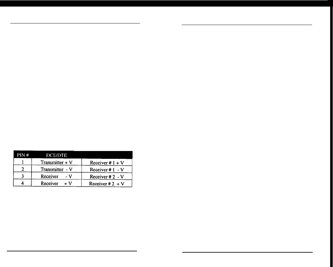
4-1 TERMINAL BLOCK DEFINITION
The four screw terminal block has different defi-
nition in different operation modes.
In the
DCE/DTE
mode, the terminal
#l
(+V) and
#2(-V) are configured to transmit data, the transmit-
ter; the terminals #3(-V) and
#4(+V)
are configured
to receive data, the receiver.
In the MONITOR mode
(for
IC-485S only), the
terminals
#l
and
#2
are respectively the positive and
negative of receiver
#I;
the terminal
#3
and
##4
are
the positive and negative of receiver
#2.
OTHERS
IC-485S/IC-485SI
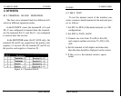
4-2 SELF TEST
To test the internal circuit of the interface con-
verter, connect a dumb terminal to the unit and proc-
ess as follows:
1. Set SW1 to DCE (if the dumb terminal is a
DTE
configuration).
2. Set SW2 to
TxON,
RxON.
3. Connect one wire from
Tx+(#l)
to
Rx+(#4),
and connect another wire from TX-(#2) to
Rx-
(#3X
4. Set the terminal to full duplex and enter data,
then the data should be displayed on the screen.
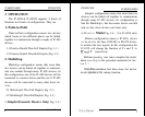
Figure 4-l Terminal Block
14
User’s Manual
User’s Manual
5. If this occurs the internal circuit is opera-
tional.
15