


TABLE OF CONTENTS
1 FUNCTION OVERVIEW
.............
1
l-l Introduction
.......................
1
l-2 Specifications.
.....................
2
2 INSTALLATION
....................
3
2-
1 Installation Procedure.
...............
3
2-2 Switch Function Description
..........
4
3 OPERATION
.......................
6
3-l Point-to-Paint/4-Wire Full Duplex
.....
8
3-2 Point-to-Paint/2-Wire Half Duplex
.....
9
3-3 Multidrop/4-Wire Full Duplex.
.......
10
3-4 Multidrop/2-Wire Half Duplex
.......
11
3-5
Simplex/Transmit,
Receive Only.
.....
12
3-6 Monitoring
(for
IC-485s
only)
......
13
4 OTHERS
..........................
14
4-
1 Terminal Block Definition.
..........
14
4-2 Self Test
.........................
15
APPENDIX A
Trouble Shooting
.....................
16
RS-232
DCE/DTE
Description
..........
17
Preventing Radio
&
TV Interference.
.....
18
FUNCTION OVERVIEW
IC-485S/IC-485SI
1 FUNCTION OVERVIEW
l-l INTRODUCTION
The IC-485S and IC-485SI are a series of a
bi-di-
rectional interface converters for RS-232 and
RS-
485. The IC-485SI has built-in isolators for high
voltage
(2OOOV)
protection. With the IC-485 series,
ic-485s
&
IC-485SI,
it provides Point-to-Point,
Multidrop and Simplex operations. The IC-485s
provides an extra Monitoring function.
The IC-485 can be powered from the following two
ways:
1)
a DC
9V,
2OOmA
power adapter
2) the pin
#9
of the RS-232 connecter
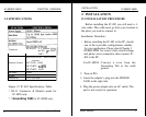
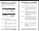
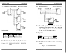
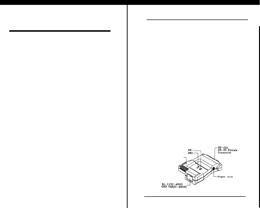
Two slide switches are used to configure its op-
eration mode, contention control, and assignment of
the RS-232. Following figure is the IC-485’s exter-
nal view.
DB-85
Female
Terminal Block
RJ-ll(ICG485S)
GND
TAB(G485SI)
Figure l-l External View
User’s Manual
1