


4 Chapter 1
Connections & Setup
PR
PB
R-AUDIO-L
VIDEO
Y
I
N
P
U
T
2
S-VIDEO
R-AUDIO-L
VIDEO
I
N
P
U
T
1
RL
A
U
D
I
O
O
U
T
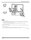
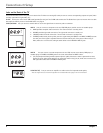
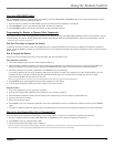
Jacks on the Back of the TV
This section describes each of the jacks on the back of the TV. When connecting A/V cables, be sure to connect corresponding outputs to inputs (video
to video, right audio to right audio, etc.)
G-LINK Connect the end of the G-LINK cable (provided) to this jack. The G-LINK cable enables the TV’s Guide Plus+ system to interact with the cable
box and/or the VCR. A picture of the G-LINK cable is on page 2.
CABLE/ANTENNA Lets you connect a coaxial cable to receive the signal from the antenna, cable or cable box.
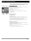
INPUT1 Lets you connect a component such as a VCR, DVD player, satellite receiver or laserdisc player.
• VIDEO provides composite video connection. The video connector is usually yellow.
• R AUDIO provides right audio connection. The right audio connector is usually red.
• L AUDIO provides left audio connection. The left audio connector is usually white.
• S-VIDEO provides better picture quality than the regular video jacks (INPUT1 and INPUT 2 VIDEO) because
the color part of the signal is separated from the black and white part of the picture. When using S-
Video, make sure to connect left and right audio cables to the R-AUDIO-L INPUT1 jacks.
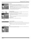
INPUT2 Lets you connect a second component such as a VCR, internet access device, DVD player, or
laserdisc player. Its AUDIO and VIDEO jacks are the same as described for INPUT1 above.
•Y, P
B
, P
R
(Component Video) provides optimum picture quality because the video is separated into three
signals. Use three video-grade cables for the connection. When using Y, P
B
, P
R
, make sure to connect left
and right audio cables to the R-AUDIO-L INPUT2 jacks.
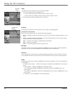
AUDIO OUT R/L Lets you connect an amplifier or audio receiver for improved sound quality.
Note: You might want to turn off the TV’s speakers from the Audio Menu. Go to page 22 for more information.