


Ridge Tool Company8
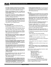
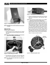
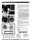
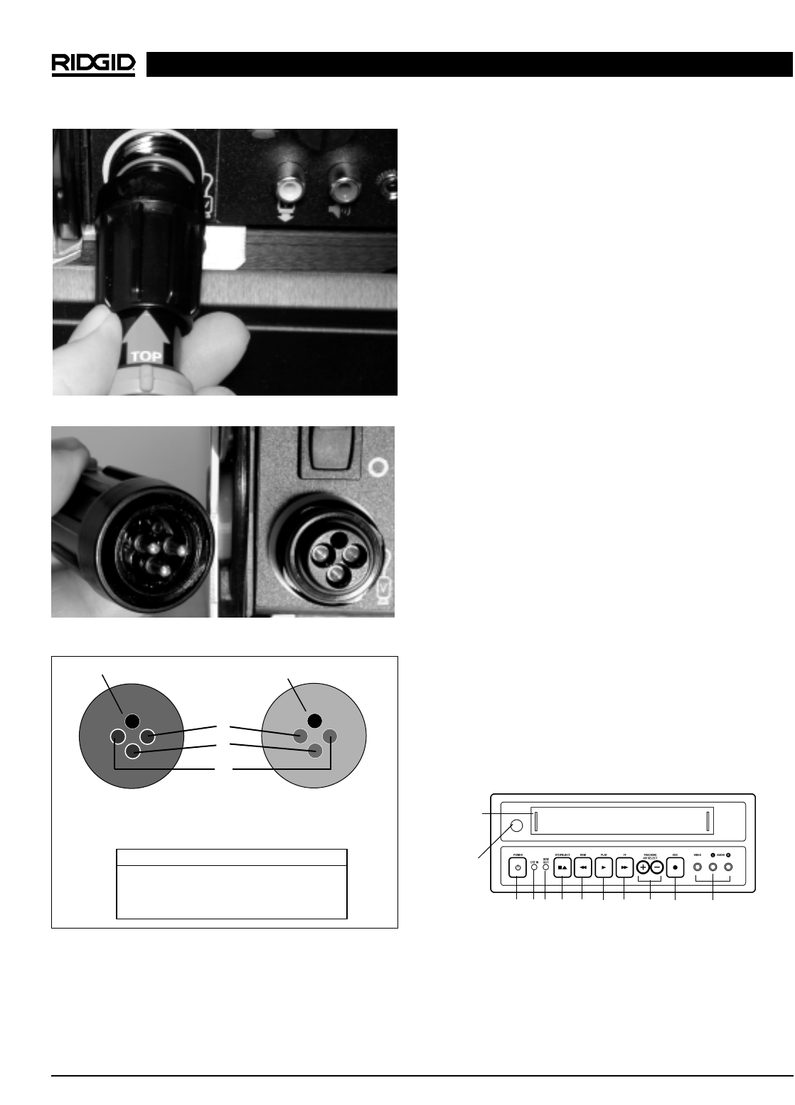
Figure 9 – Connector
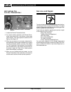
Figure 10 – Joining Connector Functions
Figure 11 – Pin Out
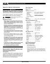
5. Turn the Power Supply ON. Be sure to first press the
reset button on the GFCI, or there will be no power to
the system. You should now have a picture on the
screen. If you have nothing on the monitor and the
power switch is illuminated (steady light), check to see
that the switch on the monitor is on. If the picture does
not look perfect, you can adjust the contrast, bright-
ness, and horizontal/vertical hold on your monitor
as well as the brightness on the camera head LED
lighting using the dimmer/transmitter knob on the
power supply.
NOTE! If your system is equipped with a SeeSnake
CountIR distance measuring device and you
want to achieve maximum accuracy, place the
camera head in the reel’s guide hoop before
turning the power on, and leave it there until
the CountIR’s start-up screen disappears. See
the CountIR Operator’s Guide for details.
NOTE! If the system is not hooked up completely (for ex-
ample, systems cable not plugged in or camera
head removed) the light on the power supply will
flash “S-O-S”. The monitor will also give indication
of improper set-up by displaying “No Cam” or “No
Dub.” A steady power switch light indicates that
the system is properly hooked up and ready for
video inspection. A slow ON and OFF flashing in-
dicates the dimmer/transmitter knob is fully
counter-clockwise – in transmitter mode.
6. When turning the system off, only the switch on the
power supply needs to be turned OFF. It is not nec-
essary to turn off the monitor or VCR separately.
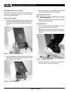
Camera Inspection
1. Put the camera head in the line and adjust the LEDs
to the desired brightness by turning the dimmer/trans-
mitter knob. If the picture does not look perfect, you
can adjust the contrast, brightness, and horizontal/ver-
tical hold on your monitor.
2. Proceed with pipe inspection as described in your
SeeSnake
®
manual, adjusting the LEDs and monitor
settings as necessary.
Recording with Your Monitor
+
VCR
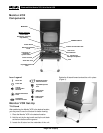
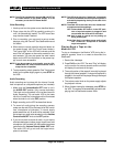
VCR Controls
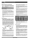
Black and White Monitor
+
VCR, Color Monitor
+
VCR
1
4
9
7
6
5
3
(1) Video Cassette Compartment
(2) Infrared Sensor
(3) Power Button
(4) Tape Loaded Indicator
(5) Dew/Hi-Fi Indicator
(6) Stop/Eject Button
(7) REW (Rewind/Reverse
Picture Search) Button
(8) Play Button
(9) FF (Fast Forward/Forward
Picture Search) Button
(10) Tracking/AV Input Select
(Front/Rear) Button
(11) Record Button
(12) Front Audio/Video Inputs
8
Pin/Socket Function
1 ..............................Neutral
2 ..............................+12 VDC
3 ..............................Video Signal
Male Connector Pins
(Systems Cable)
Female Connector
Sockets (Connector
for Systems Cable)
Guide Pin
Guide Socket
1
2
3
2
10
11
12