


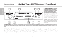
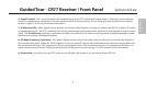
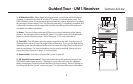
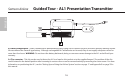

4: Squelch control - This control determines the maximum range of the CR77 before audio signal dropout. Although it can be adjusted
using the supplied plastic screwdriver, it should normally be left at its factory setting. See the “Setting Up and Using the AirLine System”
section on page 17 in this manual for more information.
5: A/B Receiver LEDs - When signal is being received, one of these will be lit green, showing you whether the (left) “A” or (right) “B” receiver
is currently being used. The CR77 constantly scans its two antennas and automatically selects whichever is receiving the strongest, clearest
signal. This True Diversity switching is completely inaudible, but it effectively increases overall range while virtually eliminating potential
interference and phase cancellation problems.
6: RF (Radio Frequency) Level meter - This “ladder” display (similar to the VU bar meter used on audio devices) indicates the strength of
the incoming radio signal. When the “100%” segment is lit, the incoming RF signal is fully modulated and at optimum strength. When only
the second most left-most “10%” segment is lit, the incoming signal is at just 10% of optimum strength. If no segments are lit, little or no
signal is being received. See the “Setting Up and Using the AirLine System” section on page 17 in this manual for more information.
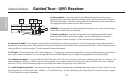
8: Power switch - Use this to turn the CR77 power on and off. When the receiver is on, the internal Power LED is lit.
7
Samson AirLine
Guided Tour - CR77 Receiver / Front Panel
ENGLISH