


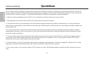
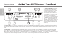
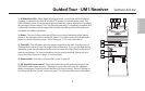
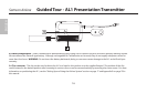

1: A/B Receiver LEDs - When signal is being received, one of these will be lit orange,
showing you whether the (left) “A” or (right) “B” receiver is currently being used. The
UM1 constantly scans its two antennas and automatically selects whichever is receiving
the strongest, clearest signal. This True Diversity switching is completely inaudible, but
it effectively increases overall range while virtually eliminating potential interference
and phase cancellation problems.
2: Meter - This set of three multicolor LEDs acts as a meter, indicating either battery
power or the strength of the incoming RF signal. This meter can also be disabled alto
-
gether to conserve battery power. See #15 on page 11 for more information.
3: Peak LED - This LED lights red when output signal from the UM1 is at the onset of
clipping (that is, when it is on the verge of being distorted). If you see this light during
operation, move the microphone further away or lower the output level of your instru
-
ment or transmitter. For more information, see the section entitled “Setting Up and
Using the AirLine System” on page 17 in this manual.
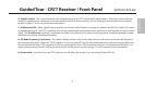
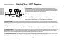
4: Power switch - Use this to turn the UM1 power on and off.
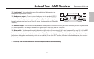
5: SQ (Squelch) Level control - This control determines the maximum range of the
UM1 before audio signal dropout. Although it can be adjusted using the supplied
plastic screwdriver, it should normally be left at its factory setting. See the “Setting Up
and Using the AirLine System” section on page 17 in this manual for more information.
9
Samson AirLine
Guided Tour - UM1 Receiver
MAX
MIN
POWER
ON
SQ LEVEL
UHF MICRO DIVERSITY RECEIVER
B
A
LOW MIDHIGH PEAK
800
MHz
2 3 1
5
7
4
6
1
+
-
ENGLISH