


Digital Video Recorder User’s Manual
25
Chapter 4. Operating
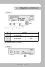
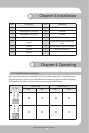
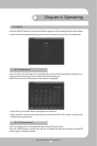
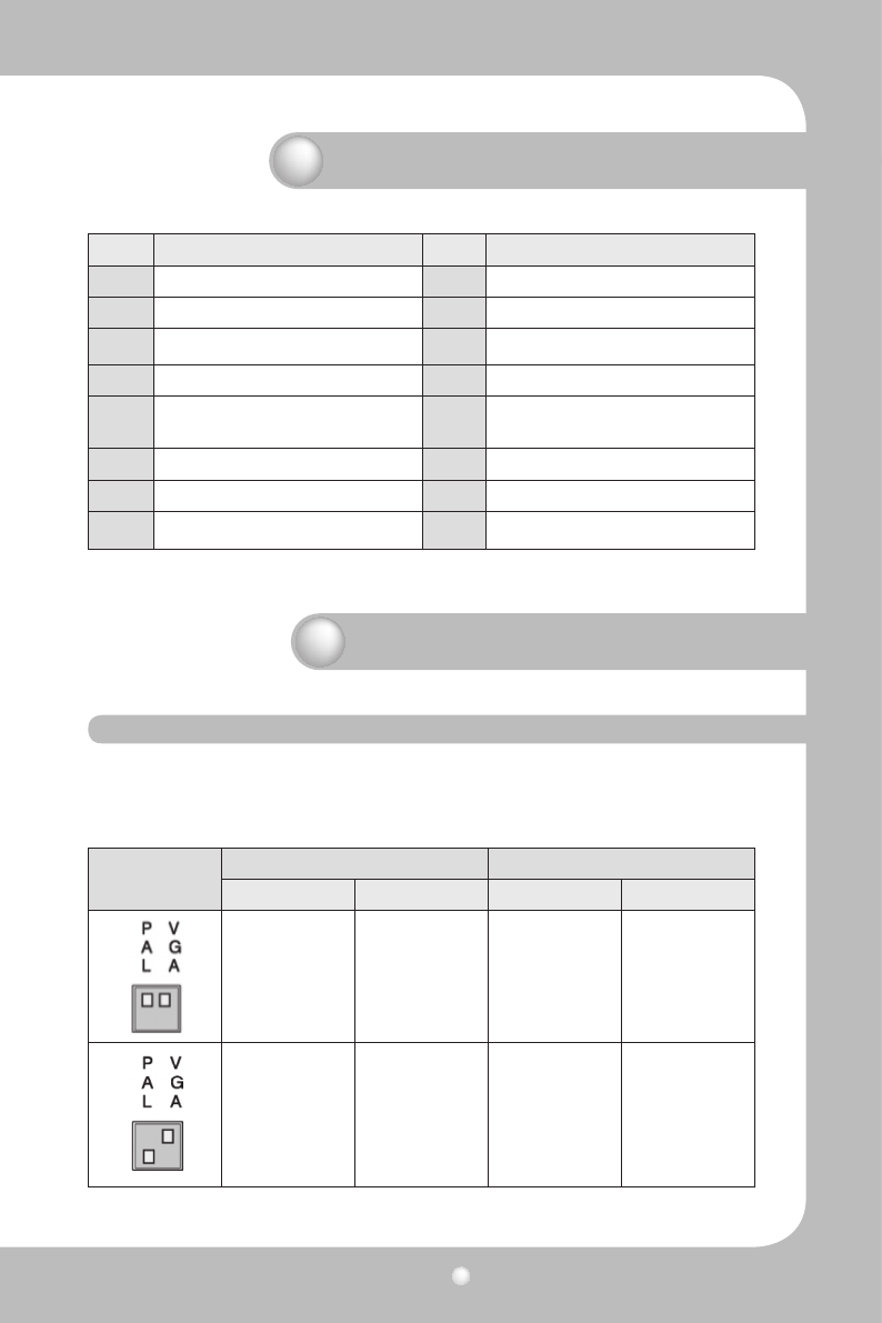
No. Description No. Description
1 Red Signal (75, 0.7Vp-p) 9 N/C(No connection)
2 Green Signal (75, 0.7Vp-p) 10 Ground
3 Blue Signal (75, 0.7Vp-p) 11 Ground
4 N/C(No connection) 12 N/C(No connection)
5 Ground 13
HSYNC (Horizontal Synchroniza-
tion)
6 Ground 14 VSYNC (Vertical Synchronization)
7 Ground 15 N/C(No connection)
8 Ground
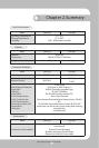
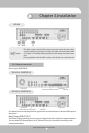
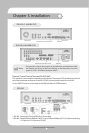
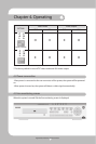
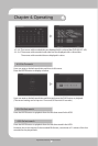
4.1 Checklist before operation
Users must select the video mode (NTSC or PAL) and video output (BNC or VGA) before pow-
ering the system on. These can be selected from the switches on the rear of the DVR system.
The settings of the video mode and video output are as described below.
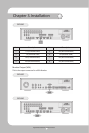
SETTING
Video mode Video output
NTSC PAL BNC VGA
O X O X
X O O X
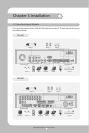
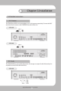
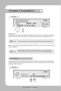
Chapter 3. Installation