


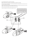
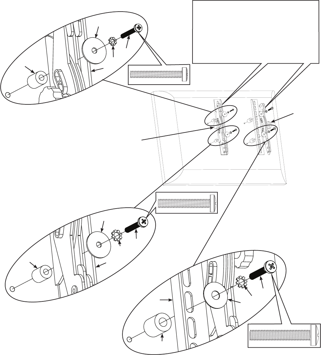
Step 2: Mount Monitor Brackets to a television with a curved back or an obstruction near the threaded insert
Determine the diameter of the Bolt (J,K,L) your TV requires by hand threading them into the threaded insert on the back of the TV. If you
encounter any resistance stop immediately.
Once you have determined the correct diameter, see the appropriate Diagram below, thread the Bolt through the appropriate Lock Washer
(M,N,O), the corresponding Washer (P,Q), the Monitor Bracket (B,C), a Spacer (R,S), and nally into the TV.
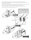
Make sure the Monitor Brackets are vertically centered and level with each other. See the appropriate Diagram below.
Tighten the Bolts (J,K,L) securing the Monitor Brackets (B,C) to the monitor.
M6
Diameter Bolt
M5
Diameter Bolt
M4
Diameter Bolt
P
C
M
J
R
P
C
N
K
R
Q
B
O
L
S
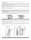
Diagram 2
Tension
Knob
Tension
Knob
NOTE: If the horizontal distance between the
threaded inserts on the back of the television
is greater than 8-1/8 inches [206 mm] but less
than 11-1/8 inches [282.5 mm], the locations of
the Monitor Brackets (B & C) may be reversed
from right to left. If the Monitor Brackets
are reversed, the Tension Knobs must be
removed and reinstalled so that they are still
facing out.