


Step 3: Mounting the Wall Plate - wood stud, brick, solid concrete and concrete block mounting options are provided
Wood Stud Installation:
CAUTION:
Do not over tighten the Lag Bolts. Tighten Lag Bolts (D) only until the Lag Bolt Washer (E) is pulled rmly against the Wall Plate
(A). If there is a layer of drywall or other material, this drywall or other material may not exceed 5/8 inch [15.8 mm] in thickness. Failure to heed
this caution may result property damage and/or personal injury
.
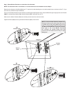
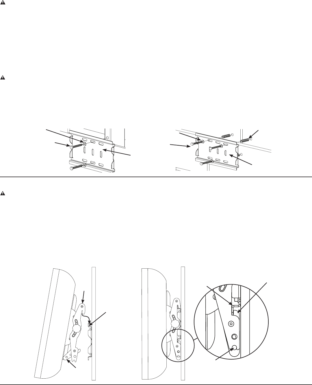
Use the Wall Plate as a template mark a location on the wall, one in the top row of slots and the other in the corresponding slot in the
bottom row. Pre-drill a 2.5” deep hole into the wood stud by using a 3/16” drill bit, making sure wall the Wall Plate is oriented to the at
surface is against the wall. Attach the Wall Plate to the wall using two Lag Bolts (D) and two Lag Bolt Washers (E). See Diagram 3A for
assistance.
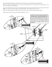
Brick, solid concrete and concrete block installation:
Use the Wall Plate (A) as a template to mark 3 locations on the wall. Two in the top row of slots and one more centered in the bottom
row.
CAUTION: Always locate Concrete Anchors (F) in the brick, block, or concrete. Never drill into the mortar between blocks.
Make sure the Concrete Anchor is seated ush with the concrete surface even if there is a layer of drywall or other material.
This drywall or other material may not exceed 5/8 inch [15.8 mm] in thickness. Failure to heed this caution may result in property
damage and/or personal injury.
Carefully pre-drill a 2.5” deep hole with a 1/2” masonry drill bit. Insert a Concrete Anchor (F) into each pre-drilled hole so it is ush with the
concrete/brick surface, even if there is a layer of drywall or other material in front; then, attach the Wall Plate (A) to the wall using three
lag Bolts (D) an three Lag Bolt Washers (E). See Diagram 3B for assistance
Step 4: Attach Monitor to Wall Plate
CAUTION: Some televisions may require two people to lift. Sanus is not responsible for personal injury or product damage.
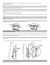
Rotate the Latch Handle into its most open position and hang the hooks of the Left and Right Monitor Brackets (B,C) over the tab on the
top of the Wall Plate (A) as shown in Diagram 4A.
Once the Monitor Brackets (B,C) are attached to the Wall Plate, rotate the Latch Handles on each Monitor Bracket until they click into
place. The tip of the Latch Handle should now be tucked up behind the tab on the bottom of the Wall Plate as shown in the Detailed View
of Diagram 4B.
You may place a padlock through the hole in the bottom of the latch handle if you wish to add security to the installation.
CSAV, Inc. and its afliated corporations and subsidiaries (collectively, “CSAV”), intend to make this manual accurate and complete. However, CSAV makes no claim that the information contained herein
covers all details, conditions, or variations. Nor does it provide for every possible contingency in connection with the installation or use of this product. The information contained in this document is subject to
change without notice or obligation of any kind. CSAV makes no representation of warranty, expressed or implied, regarding the information contained herein. CSAV assumes no responsibility for accuracy,
completeness or sufciency of the information contained in this document.
Diagram 3A
E
A
D
Diagram 3B
E
A
F
D
Diagram 4B
Diagram 4A
Latch
Handle
Top tab of
Wall Plate
(A)
Bottom tab of
Wall Plate
(A)
Hole for
Padlock
Tip of
Latch Handle
B,C