— 10 —
SERVICE ADJUSTMENTS (Continued)
WHITE BALANCE ADJUSTMENT
Composite (External Video Input)
1. Connect a color-bar generator to the external (compos-
ite) video input terminal.
2. Switch the generator to the white pattern.
3. Set the television to following conditions:
Picture: AUTO
Color Enhancer: Normal
Back Light: Bright
Display Area: 4:3
4. Enter the Service Mode. The Menu display will appear.
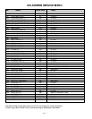
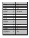
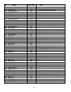
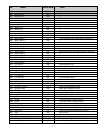
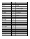
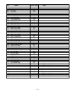
5. Select “White Balance Adjustment” Menu (No. 0BF).
6. Adjust Red, Green, and Blue Levels alternately with 1, 3,
4, 6, 7, or 9 keys to produce normal black and white
picture in highlight areas.
The White Balance Level adjustment data will be
written automatically in the Service Menu No. 08F(R),
No. 090(G), and No. 091(B).
Note: One or two data of RGB should be left at ”5C” for
normal contrast level. Do not change the data to
more than “5C.”
Other Inputs
Caution: White Balance Adjustment of Composite must
be completed before attempting other input
adjustments.
White Balance Adjustment for other modes [RF, S (Y/C),
Component (480i/ 480p)] may be unnecessary if the adjust-
ment of Composite is OK.
1. Connect a color-bar generator to the preferred video
input terminal.
2. Switch the generator to the white pattern.
3. Set the television to following conditions:
Picture: AUTO
Color Enhancer: Normal
Back Light: Bright
Display Area: 16:9
4. Enter the Service Mode.The Menu display will appear.
5. Select “White Balance Adjustment” Menu (No. 0BF).
6. Adjust Red, Green, and Blue Levels alternately with 1, 3,
4, 6, 7, or 9 key to produce normal black and white picture
in highlight areas.
The White Balance Level adjustment data will be written
automatically in the following Service Menu:
RF No 89 (R), 8A (G), 8B (B)
S (Y/C) No. 95 (R), 96 (G), 97 (B)
Component (480i) No. 9B (R), 9C (G), 9D (B)
Component (480p) No. A1 (R), A2 (G), A3 (B)
BLACK BALANCE ADJUSTMENT
Black Balance Adjustment may be unnecessary if the White
Balance Adjustment of Composite is OK.
Composite (External Video Input)
1. Connect a color-bar generator to the external (compos-
ite) video input terminal.
2. Switch the generator to the dark grey pattern (“30%
white” recommended).
3. Set the television to following conditions:
Picture: AUTO
Color Enhancer: Normal
Back Light: Bright
Display Area: 16:9
4. Enter the Service Mode. The Menu display will appear.
5. Select “Black Balance Adjustment” Menu (No. 0C0).
6. Adjust Red, Green, and Blue Levels alternately with 1,
3, 4, 6, 7, or 9 key to produce normal black and white
picture in dark grey areas. The Black Balance Level
adjustment data will be written automatically in the
Service Menu No. 092(R), No. 093(G), and No. 094(B).
Other Inputs
Caution: Black Balance Adjustment of Composite must
be completed before attempting other input
adjustments.
1. Connect a color-bar generator to the preferred video
input terminal.
2. Switch the generator to the dark gray pattern.
3. Set the television to following conditions:
Picture: AUTO
Color Enhancer: Normal
Back Light: Bright
Display Area: 16:9
4. Enter the Service Mode.The Menu display will appear.
5. Select “Black Balance Adjustment” Menu (No. 0C0).
6. Adjust Red, Green, and Blue Levels alternately with 1,
3, 4, 6, 7, or 9 key to produce normal black and white
picture in dark grey areas. The Black Balance Level
adjustment data will be written automatically in the fol-
lowing Service Menu.
RF No 8C (R), 8D (G), 8E (B)
S (Y/C) No. 98 (R), 99 (G), 9A (B)
Component (480i) No. 9E (R), 9F (G), A0 (B)
Component (480p) No. A4 (R), A5 (G), A6 (B)
1
2
3
4 5 6
7 98
RD(–)
RD(+)
BD(–)
BD(+)
(N/A)
GD(–)
(N/A)
GD(+)
(N/A)
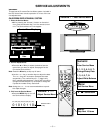
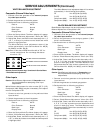
Remote Control Number keys’ functions in Service Menu
“White Balance Adjustment”
FOR RED LEVEL ADJUSTMENT
FOR BLUE LEVEL ADJUSTMENT
FOR GREEN LEVEL ADJUSTMENT


