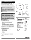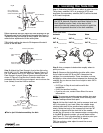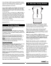
Step 5: Estimate the SAT B elevation (angle) setting you
recorded earlier, using a protractor if needed (see Figure
G). Check any obstructions at that elevation. If there are
obstructions, then select an alternate location for the dish.
0 degrees is straight toward the horizon and 90 degrees is straight upward.
IMPORTANT: When evaluating the install location,
make sure there are no trees, branches or objects
visually obstructing the dish and the general
direction of the satellite. Also, keep in mind that trees
grow up and outward and may eventually block the
signal.
You have just completed locating a site for your dish.
5. Attaching the Dish
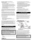
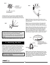
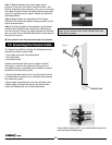
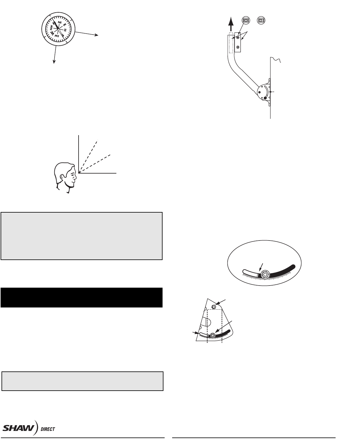
Step 1: Ensure mast is plumb before drilling any holes.
Hold the Universal Mount in place on the mounting area.
Use a carpenter’s level to plumb the antenna mast’s
straight section. If the bubble levels (horizontal and
vertical) are not centered, rotate the mast (in the curved
slot) until it is plumb. Then lock it in place by securely
tightening the Mast Adjusting Bolts (see Figure H).
IMPORTANT: Alignment of the dish will be difficult
if the mast is not plumb.
Step 2: Drill holes in the structure on which you are
mounting the dish to match the holes in the base of the
Universal Mount.
Step 3: Secure the Universal Mount with appropriate
surface screws. Check the mount for movement. An
improperly secured mount will affect dish performance.
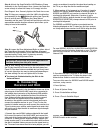
Step 4: Slide the Dish/Clamp Mount Assembly onto the
mast by loosening the (2) Azimuth Clamp Bolts (see
Figure C) and the Elevation Pivot Bolt just enough to
slide the assembly until it makes contact with the
Elevation Pivot Bolt (see Figure I). Tighten the Elevation
Pivot Bolt just enough to hold it in place on the mast.
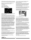
Step 5: Loosen the Elevation Adjustment Bolt 1/3 turn
from tight on either side of the Clamp Mount Assembly.
Adjust the Clamp Mount Assembly to the edge of the
white indicator line per the SAT B elevation setting you
recorded earlier. Tighten the Elevation Adjustment
Bolt (see Figure I).
SAC-00-094
90°
60°
30°
0°
Fig. G
6
Fig. G
If you live in
V
ancouver,
the satellite will be
to the Southeast
If you live in Newfoundland,
the satellite will be
to the Southwest
0
18
0
˚
90˚
2
70
˚
Fig. F
Fig. F
Use bubble level
to plumb mast so
it is vertical in all
directions
Level Not Level
Curved
slot
Fig. H
Fig. H
3
0
2
0
1
0
4
0
50
60
Elevation
Pivot Bolt
Elevation
Indicator
Elevation
Adjustment Bolt
3
0
2
0
1
0
4
0
50
6
0
When Adjusting
elevation use edge of metal
to line up with elevation setting
for your area on the elevation scale.
Use the metal edge,
not the nut or L-Bracket to
set the elevation. (For example,
in this picture, the elevation
is set at 26).
Fig. I


