


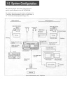
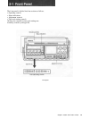
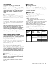
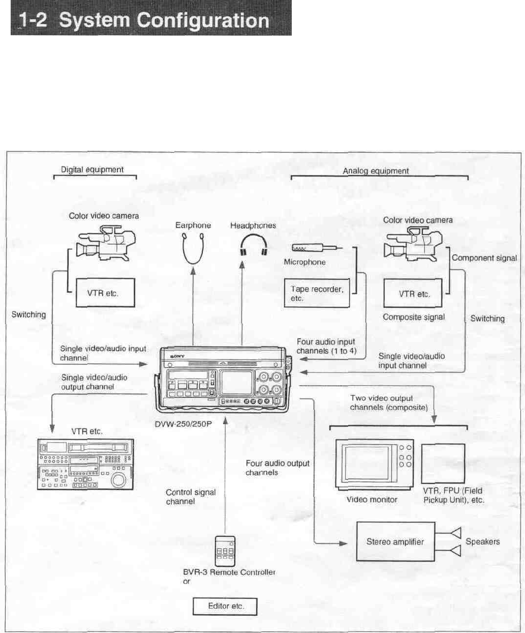
The following figure shows the configuration of a
typical system centered on the DVW-250/250P.
For details, such as the connector names, see Section 4-1-1
"Connecting Digital Equipment" (page 4-1) and Section 4-
1-2 "Connecting Analog Equipment" (page 4-2).
Typical DVW-250/250P system configuration