


20
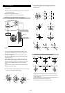
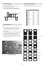
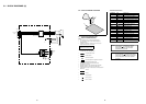
Sub Colour Adjustment
1. Receive a PAL colour bar signal.
2. Connect an oscilloscope to Pin 5 of CN003 [A Board].
3. Enter into the ‘Service’ service menu.
4. Adjust the ‘Sub Colour’ data so that the Cyan, Magenta and
Blue colour bars are of equal levels as indicated below.
Same Level
B-Out Waveform
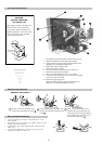
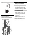
Tuner AGC Adjustment
Note:
There should be no need to adjust the AGC as this is pre-
adjusted during manufacture of the FRONTEND. If the AGC
does need adjustment then follow steps 1. to 4. below.
1. Receive a signal of 62dBuV / 75 ohm terminated via the tuner
antenna socket.
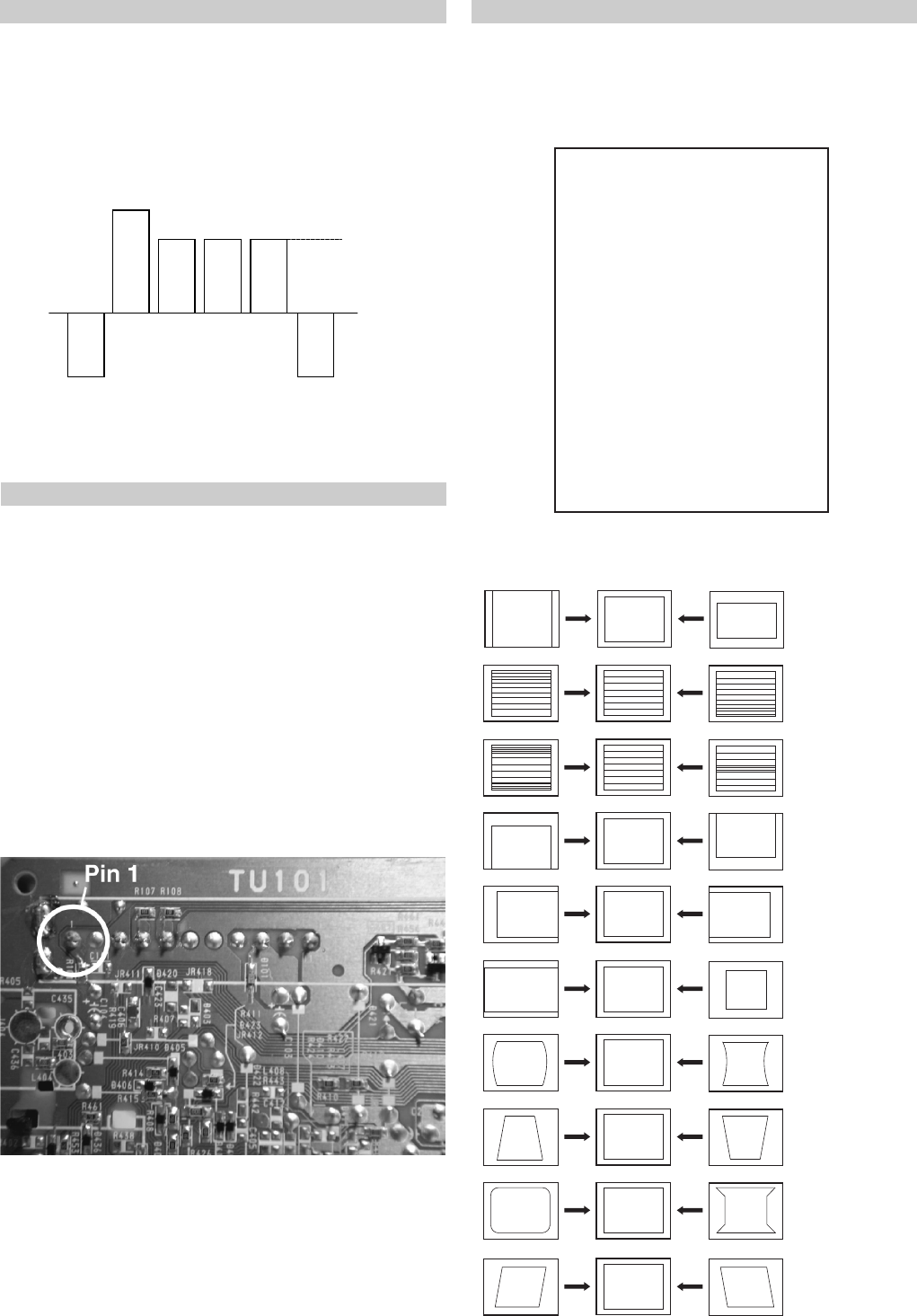
2. Connect a voltmeter to pin1 of TU101 [print side of A Board]
or to the AGC pin of CN001 [mount side of A Board].
3. Confirm that the AGC voltage is 3.5volts +/- 0.3volts.
4. If adjustment is required, then re-adjust the AGC variable
resistor (located at the top rear of the FRONTEND) to obtain
a voltage of 3.5V +/- 0.3V.
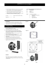
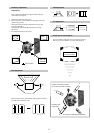
1. Enter into the ‘Geometry’ service menu.
2. Select and adjust each item in order to obtain the optimum image.
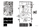
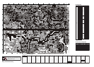
[ Print side of A board ]
Deflection System Adjustment
V SIZE
V LIN
S CORRECTION
V CENTRE
H CENTRE
H SIZE
PIN AMP
PIN PHASE
CORNER PIN
V ANGLE
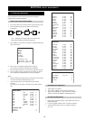
YRTEMOEG
ytiraeniL-V
llorcS-V
klBH-tfeL
klBH-thgiR
elgnA-V
woB-V
ertneC-H
eziS-H
pmA-niP
niP-renroC-U
niP-renroC-L
esahPniP
epolS-V
eziS-V
noitcerroC-S
ertneC-V
mooZ-V
atnegaM
)36,0(
)36,0(
)51,0(
)51,0(
)36,0(
)36,0(
)36,0(
)36,0(
)36,0(
)36,0(
)36,0(
)36,0(
)36,0(
)36,0(
)36,0(
)36,0(
)36,0(
)36,0(
jdA
23
8
6
jdA
jdA
jdA
jdA
jdA
jdA
jdA
jdA
53
jdA
jdA
jdA
32
04