


– 11 –
KV-J14P2S/J51PF2S
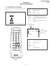
RM-869
c
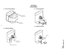
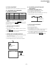
Anode button
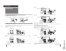
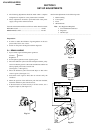
2-7. PICTURE TUBE REMOVAL
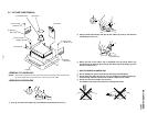
2 Using a thumb press down, then pull up the rubber cap firmly in the direction
indicated by the arrow b.
3 When one side of the rubber cap is separated from the anode button, the
anode-cap can be removed by turning up the rubber cap and pulling it up in the
direction of the arrow c.
• HOW TO HANDLE AN ANODE-CAP
1 Do not damage the surface of anode-cap with sharp shaped objects.
2 Do not press the rubber too hard so as not to damage the inside of anode-cap.
A metal fitting called the shatter-hook terminal is built into the rubber.
3 Do not turn the foot of rubber over too hard.
The shatter-hook terminal will stick out or damage the rubber.
•REMOVAL OF ANODE-CAP
NOTE : After removing the anode, short circuit the anode of the picture tube and the anode
cap to the metal chassis, CRT shield or carbon paint on the CRT.
•REMOVING PROCEDURES
1 Turn up one side of the rubber cap in the direction indicated by the arrow a.
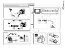
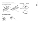
Cushion
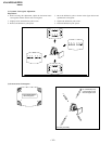
4 A board
6 C board
7 Deflection yoke
8 Four screws
(Tapping screws)
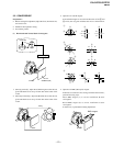
3 Anode cap
2 Speaker
block assy
1 Two screws
(+BVTP 4×16)
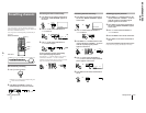
1 Two screws
(+BVTP 4×16)
2 Speaker
block assy
a
a
b
b