– 50 –
KV-PF21M70/TF21M61/TF21M90/TF21P11
RM-952
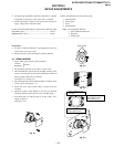
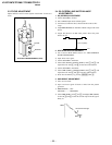
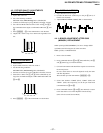
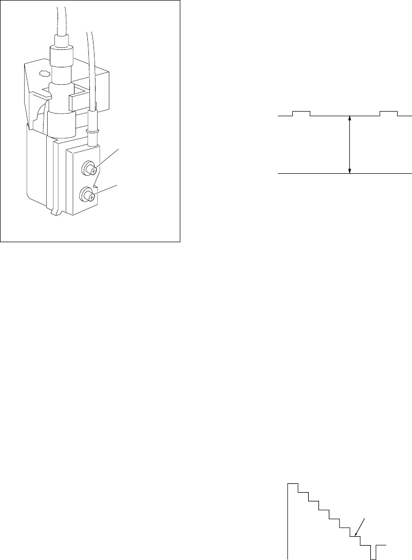
3-3. FOCUS ADJUSTMENT
Adjust FOCUS control on the flyback transformer for the best
focus.
FLYBACK TRANSFORMER (T503)
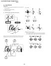
2. WHITE BALANCE ADJUSTMENT
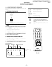
1) Set to Service Mode (Refer Section 4-1: ADJUSTMENTS
WITH COMMANDER).
2) Input white raster signal.
3) Set the PICTURE to minimum.
4) Select GCT (WHB 4) and BCT (WHB 5) with
[1] and [4], and
adjust the level with [3] and [6] for the best white balance.
5) Set the PICTURE to maximum.
6) Select GDR (WHB 1) and BDR (WHB 2) with [1] and [4], and
adjust the level with [3] and [6] for the best white balance.
7) Write into the memory by pressing [MUTING] then [0].
3. SUB BRIGHT ADJUSTMENT
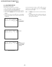
1) Set to service mode.
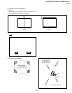
2) Input a staircase signal of black to white from the pattern
generator.
3) BRIGHTNESS ....50%.
PICTURE ............MINIMUM
4) Select SBR (WHB7) with
[1] and [4], and adjust SBR (WHB7)
level with [3] and [6] so that the second stripe from the right is
dimly lit.
3-4. G2 (SCREEN) AND WHITE BALANCE
ADJUSTMENTS
1. G2 (SCREEN) ADJUSTMENT
1) Set the PICTURE to normal.
2) Put to VIDEO input mode without signals.
3) Connect R, G and B of the C5 board cathode to the oscillo-
scope.
4) Adjust BRIGHTNESS to obtain the cathode voltage to the value
below.
5) Adjust G2 (Screen) on FBT until picture shows the point
before cut-off.
White
second from the right
Black
0 V
175 V ±2(VDC)
FOCUS
SCREEN


