


6-3
2-3. SERVO SYSTEM CHECK
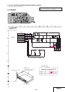
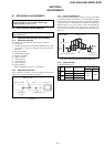
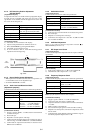
2-3-1. RF Switching Position Adjustment
(MA-405 Board)
[Adjustment Purpose]
To adjust the link of the A-ch and B-ch of the tape playback outputs.
To make the unit compatible with other tapes and units. If this
specification is not satisfied, the link will appear on the screen and
the screen will be disrupted, etc.
Mode Playback
Signal Alignment tape: SP color bar portion
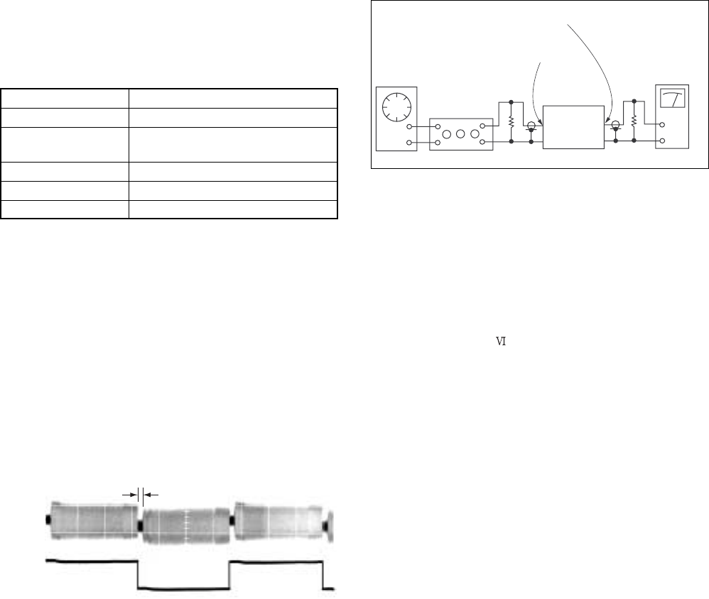
Measurement point CH1: CN270 pin 2 (PB RF)
CH2: CN270 pin 3 (RF SWP)
Measuring instrument Oscilloscope
Adjusting element Remote Commander CH+/–
Specified value A=minimize
[Adjustment Method]
1) Playback the alignment tape.
2) Short JS401 to Ground.
3) Check that “A P” is indicated on FL display.
4) Adjust so that part A becomes minimized at CH +/–.
5) Write data in EEPROM by pressing PAUSE button.
Monoral model:
6) The display “A P” disappears and then the Adjustment mode
terminates.
Hi-Fi model:
6) The display changes to “A H” and the mode goes to the HiFi
switching position Adjustment.(2-4-2.)
Fig. 6-2-3
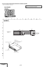
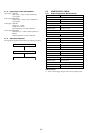
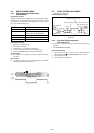
2-4. AUDIO SYSTEM ADJUSTMENT
• Adjust both L ch and R ch.
[Connecting Instruments]
Fig. 6-2-4
2-4-1. Hi-Fi Audio System Adjustment
(Hi-Fi model only)
• Perform the adjustment setting the switch on the following
positions.
• AUDIO MONITOR STEREO
[Adjustment Method]
1. ACE head adjustment.....Refer to the VHS mechanical
adjustment manual
(S
MECHANISM)(9-921-647-11).
2. E-E output level check
3. “Recording Bias Adjustment”
Audio line OUTPUT L/R
Audio line INPUT L/R
Audio oscillator
Attenuator
600 Ω
Audio level meter
or distortion meter
47 kΩ
VTR
CH1
PB RF
CH2
RF SWP
A