


Index
Index I-1
Index
A
AC IN connector 2-14
ALARM indicator 2-10
ALL CH indicator 2-5
Analog audio output section 2-13
Analog video input/output section 2-13
Audio
control section 2-4
monitor signal output section 2-16
setting display section 2-4
signal selection buttons 2-5
AUDIO OUTPUT (AES/EBU) connectors
2-14
AUDIO OUTPUT connectors 2-13
B
Basic setup menu items 8-5
C
Capstan lock mode indicator 2-6
Capstan override 2-8
Cassettes 3-8
compartment 2-2
removing when tape slack occurs 9-1
CHANNEL CONDITION indicator 2-5
Character display adjustment 3-6
Checks 9-5
COMPONENT VIDEO OUTPUT
connectors 2-14
COMPOSITE VIDEO OUTPUT
connectors 2-14
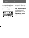
Condensation 9-4
Connections
reference video signal 3-4
to analog devices 3-2
to digital devices 3-1
to external devices 3-1
using the SDTI-CP interface 3-3
Connector panel 2-13
CONTROL PANEL connector
on the connector panel 2-15
on the switch panel 2-12
Control panels 2-1
Cooling fan 2-13
CUE OUT connector 2-13
CUE/PLAY button 2-11
Cuing up
DMC playback control points 2-9
shot marks 5-6
D
DELETE button 2-10
DF indicator 2-6
Digital
audio output section 2-14
hours meter 9-5
jog sound 1-3
signal output section 2-14
DISPLAY FULL/FINE button 2-4
DMC
EDIT button 2-10
playback 4-7
playback control section 2-10
playback control point setting buttons
2-10
DOLBY NR indicator 2-7
Drop frame mark 3-7
Dynamic motion control playback 4-7
E
EJECT button 2-2
EMPH indicator 2-5
ENTRY button 2-11
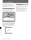
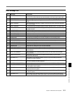
Error messages 9-2
Extended setup menu items 8-7
External device connectors 2-15
F
F FWD button 2-9
Fault display function 2-9
525/625 indicator 2-6
Format indicators 2-2
Function menu 7-1
item list 7-3
G
GOOD SHOT REC INHI indicator 2-9
Ground terminal 2-14
H
Head cleaning 9-1
I
Inspection 9-1
Interfaces 1-1
J
Jog 2-8
JOG button 2-7
JOG indicator 2-8
K
KEY INHI indicator 2-10
KEY INHIBIT switch 2-12
L
LEARN button 2-11
Level meter 2-4
LIST button 2-11
Lower control panel 2-3
LTC indicator 2-6
M
Maintenance 9-1
timings 9-6
MARK button 2-11
Memory card ejection button 2-12
Memory card slot 2-12
MEMORY indicator 2-10
Menu
control buttons 2-5
display 2-7
display section 2-6
Moisture condensation 9-4
Monitor channel L/R indicators 2-4
MONITOR OUTPUT R/L connector 2-16
MPEG IMX format 1-1
MULTI CONTROL knob 2-7
N
Normal playback 4-3
O
Operation mode 3-7
OPTION connector 2-15
OVER indicator 2-4
P
PANEL SELECT switch 2-12
Panels
connector panel 2-13
lower control panel 2-3
switch panel 2-12
upper control panel 2-2
PB controls 2-5
PHONES jack/control 2-2
PLAY button 2-9
PLAY IN/OUT button 2-10
Playback 4-1
at normal speed 4-3
format indicator 2-6
in jog mode 4-3
in shuttle mode 4-4
in variable speed mode 4-4
preparations 4-1
procedures 4-3
storing varying playback speed 4-7
using capstan override 4-5
with SDTI-CP output 4-2
Post marks 5-3
Power supply section 2-14
POWER switch 2-2
PREROLL button 2-9