


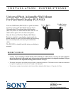
Installation Instructions Pitch-Adjustable Mount PLP91/D
3
INSTALL MOUNT
Install the mount as follows:
1. Determine the exact mounting location prior to installation and
draw a level line to indicate the desired height for the top of the
mounting plate.
WARNING: Improper installation can result in serious per-
sonal injury! Make sure that the structural
framework can support a weight factor five times
the total weight of the equipment. If not, reinforce
the structure before installing the mount.
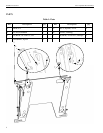
2. With the mount correctly oriented and level, secure the mount
to the wall (see Figure 1) using four fasteners (not included).
Fasteners must be driven into the supporting wall studs or other
supporting framework.
3. Check mount to ensure it is level and adjust to level if
necessary.
INSTALL DISPLAY BRACKETS
Install display bracket(s) according to the instructions provided.
The bracket(s) is/are designed for your specific model.
MOUNT THE DISPLAY
Mount the display as follows:
1. Make sure no power is supplied to the display and the flags are
in the lowered (open) position before attempting to mount the
display.
2. Using two people, slide the display down over the mount.
Make sure all four Q-buttons of the display engage all four
slots in the mount.
3. With the Q-buttons of the display fully engaged in the slots of
the mount, secure the display on the mount by raising the flags
all the way to their locked position. If the flags do not fully
engage, remove the display and make sure the brackets are
correctly installed.
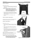
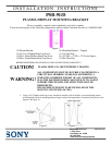
NOTE: A security lock may be installed through the hole in the
locking flag for additional security (see Figure 2).
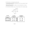
NOTE: If display does not remain at desired tilt setting, tighten
the nut and bolt on tilt arms on each side (see Figure 3).
WARNING: Make sure the flag securing the display is com-
pletely lowered at all times except when removing
or installing the display. The flag must be all the
way down when installing/removing cables.
Figure 2. Optional Security
Security Lock May Be
Installed
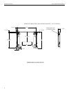
Mounting
Holes
Mounting
Holes
Figure 1. Mounting Hole Locations
to adjust tilt tension
Loosen or tighten
to adjust tilt tension
Loosen or tighten
this nut
this bolt
Figure 3. Tilt Tension Adjustment