


25 (US)
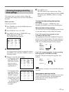
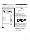
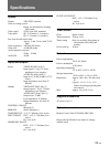
REMOTE jack
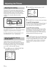
This VCR can be remotely controlled by adding the
circuit shown below to the REMOTE jack or by using
the SVT-RM10 Remote Control Unit (not supplied).
Note
Use a shielded cable less than 5 m (16 ft.) in length.
SW3
SW4
SW5
SW6
SW7
SW8
SW2
SW1
SW9
SW10
SW11
SW12
R2
R3
R4
R5
R6
R7
R8
R9
R10
R11
R12
R13
1.5K
0.43K
0.51K
0.62K
0.75K
0.91K
1.1K
1.3K
2.0K
2.4K
3.6K
5.6K
SW1 ......... STOP
SW2 ......... PAUSE
SW3 ......... REW
SW4 ......... FF
SW5 ......... PLAY
SW6 ......... REC
SW7 ......... MENU
SW8 ......... REV PLAY
SW9 ......... TRACKING/DATA –
SW10 ....... TRACKING/DATA +
SW11 ....... SHIFT v
SW12 ....... SHIFT b
Resistor tolerance should be equal
to or less than ±2%.
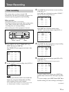
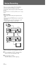
REMOTE jack
Using recording status output signal
Using a stereo miniplug to output the recording status
signal from the REMOTE jack. The pin allocation of
the Remote IN and Recording Status OUT is as shown.
The recording status output signal functions as
follows:
• When recording: 5 V signal is output.
• During recording pause: the signal slowly turns on
and off repeatedly (about 1 Hz).
• If something is wrong with recording: the signal
rapidly turns on and off repeatedly (about 4 Hz).
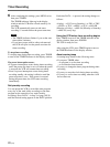
• At the end of the tape: the signal turns on about one
second, then turns on and off rapidly twice
(equivalent to 4 Hz).
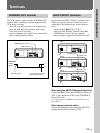
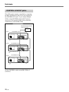
When using the SVT-RM10 Remote Control
Unit
When the SVT-RM10 Remote Control Unit (not
supplied) is connected to the REMOTE jack, the REC/
PLAY SPEED $/4 buttons on the SVT-RM10
function the same as the TRACKING/DATA +/–
buttons on the VCR.
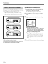
When using the FS-20 Foot Switch
To connect the FS-20 Foot Switch (not supplied) to the
REMOTE jack, an internal modification is required.
Consult your Sony dealer.
Ground
Recording Staus OUT
Remote IN
1 sec. 1 sec.
5 V
0 V