


Chapter 5: Advanced Motherboard Setup
5-7
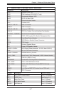
Jumper Description Default Setting
JPB1 BMC (IPMI) Enable/Disable Pins 1-2 (Enabled)
JBT1 CMOS Clear See Section 5-9
JWD1 Watch Dog Timer Pins 1-2 (Reset)
JWP1 BIOS Write Protect Pins 1-2 (Enabled)
JPUSB1 USB Wake-up Pins 1-2 (Enabled)
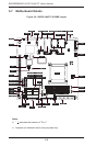
X9SPV-LN4F/F-3610ME Quick Reference
Connector Description
LED1 Standby Power LED
LED2 IPMI Heartbeat LED (X9SPV-F only)
LED3 Unsupported Memory LED
SLOT1 PCI-E x16 Gen 2 Slot
JL1 Chassis Intrusion Header
JOH1 Overheat LED
USB 0/1, USB 2/3 USB 3.0 Headers
USB 6/7 USB 2.0 Header
USB 4/5, USB 8/9 Backpanel USB Ports
FAN1~4 CPU Fan, System Fan and Auxilliary Fan Headers
T-SGPIO1, T-SGPIO2 Serial General Purpose I/O Headers
JPI2C1 JPI2C, PWR supply (I2C) System Management Bus
JF1 Front Panel Control Header
JSD1 DOM (Disk on Module) Power Connector
JTPM1 TPM Header
SP1 Onboard Speaker/Buzzer
JD1 Power LED/Speaker Header
I-SATA1~I-SATA6 SATA Ports (White connectors: SATA 3, Black: SATA 2)
JPW1 24-Pin ATX Power Connector
DIMMA1, DIMMB1 SODIMM Memory Sockets
COM1, COM2 Serial Ports (COM1: Backpanel, COM2 Onboard Header)
IPMI IPMI Port (X9SPV-F only)
KB/MOUSE Combination PS/2 Keyboard or Mouse Port
LAN1, LAN2 LAN1, LAN2 Gb Ethernet Ports
LAN3, LAN4 LAN3, LAN4 Gb Ethernet Ports (X9SPV-LN4 only)
VGA VGA Port
JIPMB1 4-pin External BMC I2C Header (for an IPMI card)
CPU1 CPU / Processor