


Chapter 5: Advanced Serverboard Setup
5-17
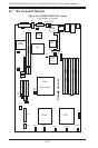
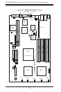
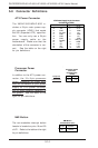
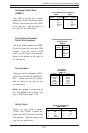
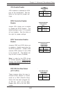
Fan Headers
There are ten fan headers (FAN1-
FAN10) on the X6DHP-8G/X6DHP-
8G2. These fans use DC power.
See the table on the right for fan
pin definitions.
Note: Fan speed is controlled by
the "Fan Speed Control Mode" set-
ting in BIOS (see page 7-16).
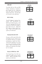
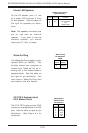
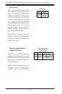
Universal Serial Bus
(USB0/1)
Two USB 2.0 ports are located
beside the GLAN (Ethernet) ports.
USB0 is the bottom port and USB1
is the top port. See the table on
the right for pin definitions.
Universal Serial Bus Pin Definitions
Pin
Number Definition
1+5V
2P0-
3P0+
4Ground
5 N/A
Pin
Number Definition
1+5V
2P0-
3P0+
4 Ground
5Key
USB0
USB1
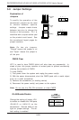
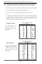
Serial Port Pin Definitions
(COM1/COM2)
Pin Number Definition
1 CD
2 RD
3 TD
4 DTR
5 Ground
Pin Number Definition
6 DSR
7 RTS
8 CTS
9 RI
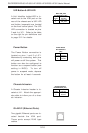
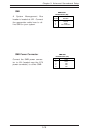
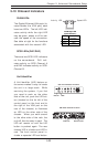
Front Panel Universal
Serial Bus Headers
Two extra USB headers (at USB2/
3) can be used for front side USB
access. You will need a USB
cable to use these connections.
Refer to the tables on the right for
pin definitions.
Front Panel Universal Serial Bus
Pin Definitions
Pin
Number Definition
1+5V
2P0-
3P0+
4Ground
5 N/A
(USB2/3)
Serial Ports
There are two COM headers
(COM1 and COM2) located be-
tween the SCSI Channel A and the
IDE headers. See the table on the
right for pin definitions.
Fan Header
Pin Definitions
(FAN1-10)
Definition
Fan PWR
Tachometer
GND
GND
Tachometer
Fan PWR
Pin #
1
2
3
4
5
6
Color
Red
Yellow
Black
Grey
White
Orange