


26
Connecting your TV
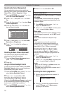
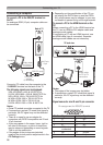
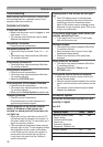
Connecting a computer
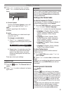
To connect a PC to the RGB/PC terminal on
the TV:
AnanalogueRGB(15pin)computercablecan
beconnected.
PC/
HDMI1
(
AUDIO
)
RGB/PC
Computer
Audio cable
for PC-to-TV
connection
Conversion
adapter
(if necessary)
RGB PC cable
Mini D-sub
15 pin
Back of TV
ConnectaPCcablefromthecomputertothe
oRGB/PCterminalonthebackoftheTV.
The following signals can be displayed:
VGA:VESA640×480@60/72/75Hz
S-VGA:VESA800×600@56/60/72/75Hz
XGA:VESA1024×768@60/70/75Hz
W-XGA:VESA1280×768@60/75Hz
W-XGA:VESA1360×768@60Hz
S-XGA:VESA1280×1024@60/75Hz
Notes:
•SomePCmodelscannotbeconnectedtothisTV.
•IfconnectingacertainPCmodelthatsignalis
particular,thePCsignalmaynotbedetected
correctly.
•Thereisnoneedtouseanadapterfor
computerswithDOS/VcompatibleminiD-sub
15 pin terminal.
•Abarmayappearintheupper,lower,rightor
left side of the screen, or parts of the picture
may be obscured depending on some signals.
Thisisnotthemalfunction.
•Iftheedgesofthepicturearestretched,
readjustthepicturepositionadjustmentsinthe
PC Settings menu.
•DependingonthespecicationofthePCyou
areplayingtheDVD-Videoon,andtheDVD’s
title, some scenes may be skipped, or you may
notbeabletopauseduringmulti-anglescenes.
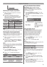
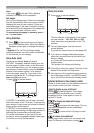
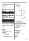
To connect a PC to the HDMI terminal on the
TV:
WhenconnectingaPCtotheHDMIterminalon
theTV,useanHDMI-toDVIadaptercableand
analogueaudiocables.
IfconnectingaPCwithanHDMIterminal,use
anHDMIcable(typeAconnector).Separate
analogueaudiocablesarenotnecessary.
1 2 3 4
PC/
HDMI1
(
AUDIO
)
TV back view
TV back view
Computer
Audio cable
for PC-to-TV
connection
Notes:
•Theedgesoftheimagesmaybehidden.
•IfconnectingacertainPCmodelthatsignalis
particular,thePCsignalmaynotbedetected
correctly.
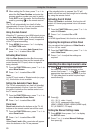
Signal names for mini D-sub 15 pin connector
Pin assignment for RGB/PC terminal
Pin No. Signal name Pin No. Signal name
1 R 9 NC
2 G 10 Ground
3 B 11 NC
4 NC(not
connected)
12 NC
5 NC 13 H-sync
6 Ground 14 V-sync