


to check the operation of the signal. If the
signal is missing or improper, the main board
is most likely at fault.
4. Play a CD and check the tracking error signal
at TP507
5. Check for a focus or tracking problem at pins
1, 2, 3, and 4 of CN501. These are the focus
and tracking drive signals going to the laser
slide assembly. You should see an ac signal
riding on about 4 volts dc.
6. If the drive signals are being loaded down,
remove power from the player and unplug the
flex cable to CN501.
7. Plug the player in and turn on the power
while monitoring pin 1 of CN501. The drive
signal rises to 4 volts dc if it’s good. This
also applies to the other drive signals on pins
2, 3, and 4.
8. For DVD tracking problems check the track-
ing error signals going to the main board on
pins 12, 13, 14, and 15 of CN501.
9. For CD tracking problems check the tracking
error signals going to the main board on pins
ten and eleven of CN501.
10. If the focus coil does not move up and down
or the laser does not come on, check for plus
5 volts on pin 19 of CN501 and plus 2 volts
on pin 20 of CN501.
11. If the voltages are missing or improper,
unplug the flex cable and measure them
unloaded.
12. For problems associated with the feed motor
or the spindle motor check the signals on
connector CN502.
13. Check the feed motor drive signals at pins 1
and 2 of CN502. They are easiest to see
when the power is cycled on and the player is
put in the times 8 scan speed.
14. These signals can also be checked unloaded;
however, the drive signal goes to 4 volts DC
when AC is applied and power is turned on.
If the dc signal is present, the drive signal
from the main board is good.
15. To check the feedback from the feed motor
hall switches, monitor pins 5, 6, 7, and 8 of
CN502 while cycling power and playing a
disc in times 8 scan.
16. If a disc won’t play you can still check the
hall switches, turn the power off and push the
slide away from the spindle motor. Then turn
the power on and monitor the signals as the
slide moves back to its default position.
17. The dc drive voltage for the feed motor hall
switches is monitored at pin 3.
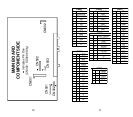
18. The spindle motor drive signals are checked
at pins 17, 18, and 19. They are easiest to see
when the power is cycled on and the player is
put in the times 8 scan speed.
19. These signals can also be checked unloaded;
however, you can only see a momentary
12 13