


10
HLC56 (E/F) Web 213:276
Chapter 2: Connecting your Monitor
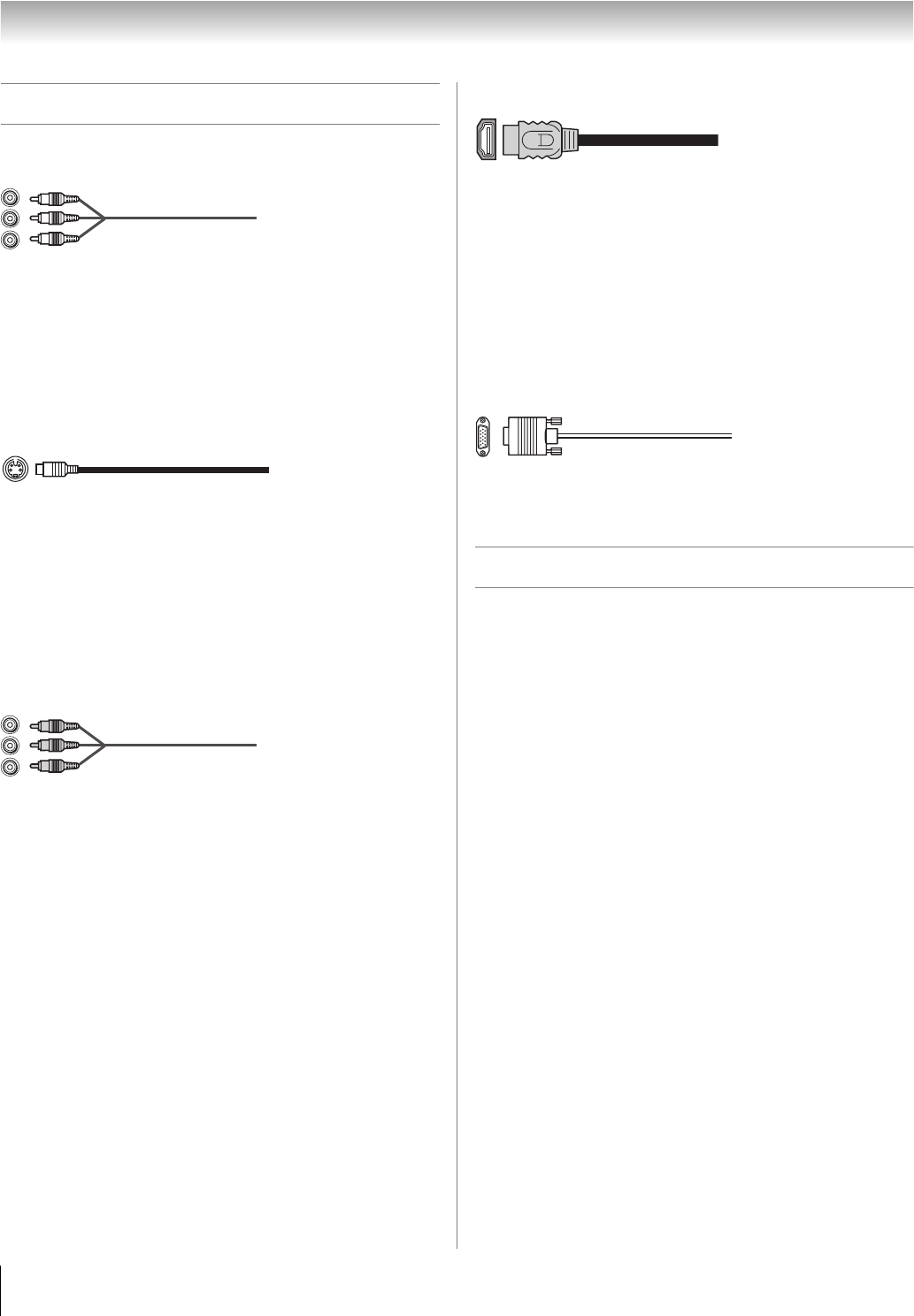
Overview of cable types
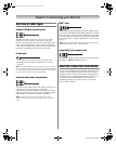
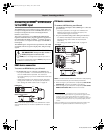
Standard A/V cables (red/white/yellow)
Standard A/V cables (composite video and analog audio)
usually come in sets of three, and are for use with video
devices with analog audio and composite video output. These
cables (and the related inputs on your monitor) are typically
color-coded according to use: yellow for video, red for stereo
right audio, and white for stereo left (or mono) audio.
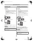
S-video cable
S-video cable is for use with video devices with S-video
output. Separate audio cables are required for a complete
connection.
Note: An S-video cable provides better picture performance
than a composite video cable. If you connect an S-video cable,
be sure to disconnect the standard (composite) video cable or
the picture performance will be unacceptable.
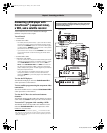
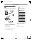
Component video cables (red/green/blue)
Component video cables come in sets of three and are for use
with video devices with component video output.
(ColorStream
®
is Toshiba’s brand of component video.) These
cables are typically color-coded red, green, and blue. Separate
audio cables are required for a complete connection.
Note: Component video cables provide better picture
performance than a standard (composite) video or S-video
cable.
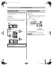
HDMI
™
cable
HDMI (High-Definition Multimedia Interface) cable is for use
with devices with HDMI output. HDMI cable delivers digital
audio and video in its native format. HDMI cable carries both
video and audio information; therefore, separate audio cables
are not required for a complete HDMI device connection (-
page 14).
Note: HDMI cable provides better picture performance than a
standard (composite) video or S-video cable.
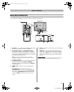
Analog RGB (15-pin) computer cable
Analog RGB (15-pin) computer cable is for connecting a PC to
the monitor’s PC IN terminal (- page 15).
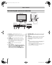
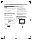
About the connection illustrations
You can connect different types and brands of devices to your
monitor in several different configurations. The connection
illustrations in this manual are representative of typical device
connections only. The input/output terminals on your devices
may differ from those illustrated herein. For details on
connecting and using your specific devices, refer to each
device’s owner’s manual.
263237HLC56_EN.book Page 10 Monday, June 5, 2006 3:46 PM