


PPaaggee 66
MMRRFF--220000 BB
AASSEE
SS
TTAATTIIOONN
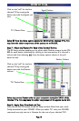
with the enclosed screws, then the receiver is slid back into place.
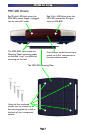
SStteepp 33 -- CCoonnnneecctt tthhee PPoowweerr SSuuppppllyy aanndd IInnsseerrtt tthhee BBaatttteerriieess
Connect the 9V power supply to an active UNSWITCHED AC outlet. The MRF-
200 must always be powered up to operate.The red P
OWER LED should light.
Insert the batteries in the MX-800 remote control.
SStteepp 44 -- TTeesstt tthhee MMXX--880000
Observe the MRF-200’s STATUS LED blinking while you press and hold a pro-
grammed button (one with an actual command).This tells you that the MRF-
200 is receiving the RF commands of the MX-800.
SStteepp 55 -- OOrriieenntt tthhee AAnntteennnnaa ffoorr OOppttiimmuumm RRaannggee
If you need to extend the range of the remote, try adjusting the angle of the
MRF-200 receiving antenna via it’s pivoting ball mount.
SStteepp 66 -- TTeesstt OOppeerraattiioonn WWiitthhoouutt FFllaasshheerrss
With the MX-800’s IR output blocked by a jacket or pillow, test the control of
your components using just the Front Blaster. In most cabinets, the MRF-200’s
Front Blaster will control any A/V components in the same cabinet space by
reflections from the cabinet walls and doors. Make sure that the components
operate with the cabinet doors closed or open. If a component is placed too far
away from the front blaster, you will need to utilize the included Flashers plugged
into the MRF-200’s rear Flasher Line Output jacks.
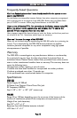
If you have problems with components that are close to the Front Blaster, see
the next page and the section on Front Blaster Overload.
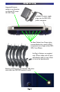
SStteepp 77 -- CCoonnnneecctt FFllaasshheerrss ttoo OOuutt ooff SSiigghhtt AA//VV CCoommppoonneennttss
IImmppoorrttaanntt NNoottee:: TTeesstt tthhee ooppeerraattiioonn BBEEFFOORREE ssttiicckkiinngg tthhee ffllaasshheerr iinn ppllaaccee..
Use a flashlight to identify the correct location of the component’s IR sensor,
then try a few commands while moving the flasher around the face plate of
the component. The most reliable operation typically occurs a half inch or so
away from the IR sensor.
Once you have found the spot that gives the most reliable operation, peel off
the protective backing of the self-adhesive tape on the included Flashers and
stick them in place.
IImmppoorrttaanntt NNoottee:: AAllwwaayyss rreeppllaaccee tthhee sseellff--aaddhheessiivvee ttaabbss iiff yyoouu hhaavvee ttoo rreeppoossii--
ttiioonn aa ffllaasshheerr.. SSiixx eexxttrraa sseellff--aaddhheessiivvee ttaabbss aarree ssuupppplliieedd ffoorr tthhiiss ppuurrppoossee..