


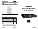
iPUMP 6400 QUICK START GUIDE iPUMP 6400 QUICK START GUIDE
800009-03 Rev. A 8 Professional Video Professional Video 5 800009-03 Rev. A
The liquid crystal display (LCD) provides menu, data, and input
screens to the user. Menu screens are entry points to further
screens showing signal or unit status or to user-input screens that
can be changed by the user. The "home" screen displays the
iPump unit's Serial Number, Eb/N0, and alternately displays FEC
Ratio, Signal Frequency, and Transport Rate. This screen may be
reached at any time by repeatedly pressing the ESC button.
Six pushbuttons allow you to move through the various screens,
select characters for input, and accept or reject changes. To move
downward or upward through the menu screens, use the ENTER
and ESC buttons. To enter or change data in editable fields, press
the ENTER button and use the up rr and down ss arrow buttons to
increment the highlighted character or digit. Use the right ww and
left vv arrow buttons to move to adjacent digits and press ENTER
again to accept your input. Pressing ESC before accepting your
input will cancel any changes.
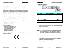
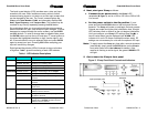
Eight light-emitting diodes (LEDs) illuminate to show unit status
at a glance. Table 1 gives the meaning of each LED indicator.
Table 1. LED Indicator Descriptions
LED Label Color and State Meaning
GREEN constant Receiver is tracking carrier.CARRIER
GREEN slow blink Receiver is not tracking carrier.
GREEN constant iPump is recording a program.RECORD
Off iPump is not recording.
GREEN constant iPump is downloading a file via Compel.DOWNLOAD
Off iPump is not downloading.
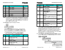
GREEN constant
Light network activity over the iPump's LAN
interface.
GREEN slow blink Heavy network activity over the iPump's LAN
interface.
LAN
Off iPump observed no packet transfers during the
last 20 secs.
GREEN constant iPump has received a Compel command
within the last two minutes.
GREEN fast blink iPump has been addressed by Compel within
the last five seconds.
COMPEL
GREEN slow blink iPump is in tracking mode and Compel is
required but no Compel command received
within the last two minutes.
4. Next, start your iPump as follows:
a. Connect the ac power cord to the iPump's IEC
receptacle (ff, Figure 1) and to a 100-to-120-Vac or 200-to-240-
Vac source.
b. Set the power switch to the On position ( I ) and
press and hold the ENTER button on the front panel for two
seconds. The iPump will power up and begin the boot process.
Outputs are muted during the short initialization time. All eight
LED indicators flash on and off as the unit begins initialization.
Until you configure your iPump's RF settings (see Step 66), a
loss-of-carrier alarm may be displayed (red ALARM LED
indicator is lit and LCD screen indicates the alarm state). RF
settings are not necessary for units with the optional ASI input.
Note: To easily restart the iPump any time after a normal shutdown
(see Step 9), simply press the ENTER button on the iPump’s
front panel (refer to the User's Manual for details). If the
receiver is tracking a carrier signal, the green CARRIER LED
will light.
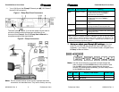
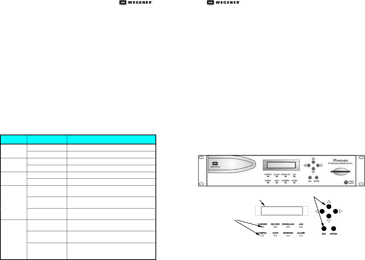
5. Get to know the iPump's front panel
Figure 3. iPump Front-Panel Controls and Indicators
Liquid Crystal Display (LCD)
Pushbuttons
LED Indicators