


Installation
20 800032-01 Rev. G www.wegener.com
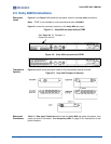
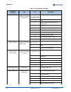
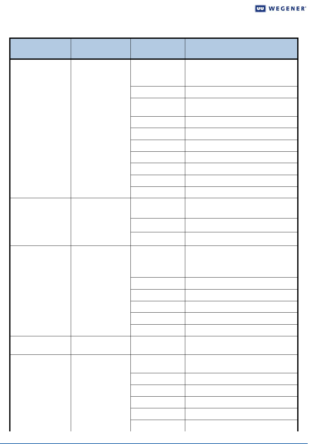
Table 2.1: Rear panel Connectors
Connector
Designation
Type Pin Signal Name
ALARM/CUEING 10-pin male header
(mates to removable
terminal-strip)
1
(on left as viewed
from rear of unit)
OK (COM closes here when OK)
2 COM:
3 Alarm (COM closes here on alarm or if
power is off)
4 GND
5 Cue Relay #1: N.C. contact
6 Cue Relay #1: Common contact
7 Cue Relay #1: N.O. contact
8 Cue Relay #2: N.C. contact
9 Cue Relay #2: Common contact
10 Cue Relay #2: N.O. contact
DTMF
(where available)
3-pin male header
(mates to removable
terminal-strip)
1 (on left as viewed
from rear of unit)
DTMF tone, non-inverted output
2 GND
3 DTMF tone, inverted output
AUDIO
(same for both
ports 1 and 2)
6-pin male header
(mates to removable
term strip)
1 (on left as viewed
from rear of unit)
Right ‘+’
2 Right GND
3 Right ‘-’
4 Left ‘+’
5 Left GND
6 Left ‘-’
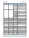
COMPOSITE VIDEO
OUT
BNC Jack Composite Video Out
SERIAL CONTROL RS232, 9-pin D
female jacks
1 DCD (internally pulled to +5V)
2 RxD (data output)
3 TxD (data input)
4 DTR (not connected)
5 GND
6 DSR (internally pulled to +5V)