17
Wiring
Wiring the system:
This unit requires a +13.8 VDC fused circuit. Unit draws up to 3 amps. The unit uses sophisticated micro-
processor technology and needs “clean” (filtered) power to function properly.
DO NOT USE power designated to operate a +12 VDC lighting circuit from the converter, or a con-
verter that does not have a battery connected to it, or any unfiltered converter! Damage to the
system could result!
If in doubt, contact your dealer or the manufacturer of your vehicle.
NOTE: See page 5, Operation section, of this manual for one and two receiver set-
ups.
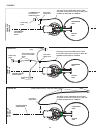
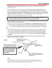
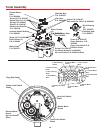
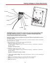
1. Make connection of the RED WIRE to +13.8 VDC (constant supply of power).
DO NOT HOOK UP ORANGE WIRE. This is for “Antenna Up” warning sensor
supplied by most RV manufacturer. DO NOT CONNECT ORANGE WIRE TO +13.8 VDC!
Connect the BLACK WIRE to the ground.
2. Connect the “BRIGHT WHITE” (PRIMARY) COAX CABLE to “Satellite In” jack on the
back of your receiver. The primary coax must be hooked to the electronics box. This
receiver controls the toggle function.
3. Connect the receiver “Out to TV” to the television.
4. Plug receiver into 117 VAC receptacle.
5. Connect the other cable to your second receiver/TV.
For proper operation:
1. To check for LNBF voltage, you must have your receiver connected to your
system. Lack of receiver or a bad connection at some point will result in the dish not
being able to lock on any satellite signal. All LEDs on wall plate control panel will be on until cor
rected.
2. Refer to the Operation Section to fully test the system!
Check Switch function and toggling between satellites
For a complete description of these functions, see Operation section.


