9
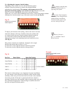
Fig 3.6
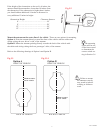
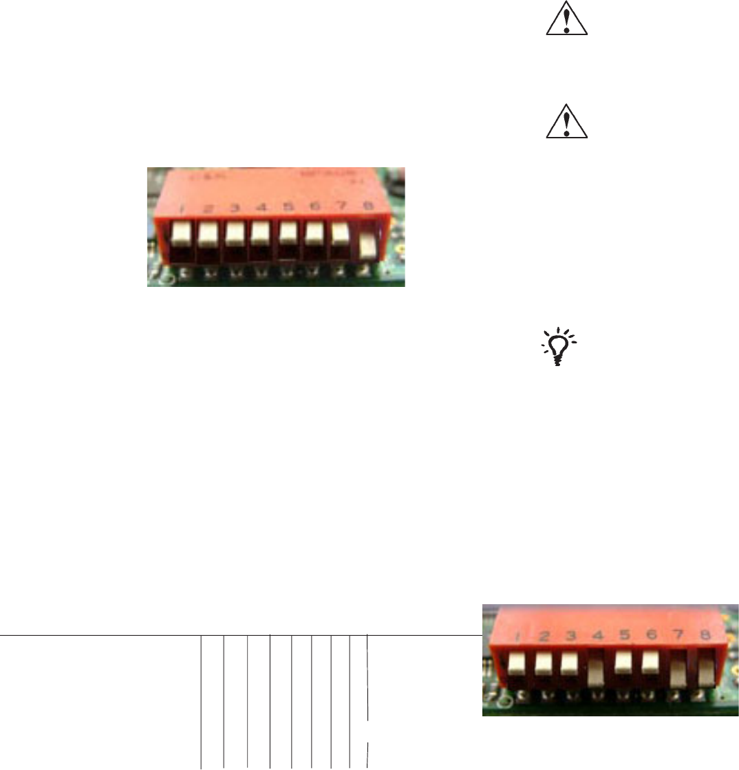
Sat. Rcvr. Mount Option Switch Set Position
1 2 345678
DISH NETWORK ................. A...................... 0 ... 0 ..... 0 .... 1 .... 0 .. 0 .. 1 .. 1
DISH NETWORK ................. B...................... 1 .... 0.... 0 .... 1 .... 0 .. 0 ... 1 .. 1
DIRECTV ............................. A...................... 0 .... 0..... 0 .... 0 .... 0 .. 0 ... 0 .. 1
DIRECTV ............................. B...................... 1 .... 0..... 0 .... 0 .... 0 .. 0 ... 0 .. 1
Antenna switches may
need to be adjusted prior to
operating the system.
Refer to Section 1,
Fig. 1.1, for Main Control
Board location.
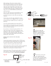
Example
Switches set for DISH Network,
mount option A.
Fig 3.5
Switches set for DirecTV
mount Option A.
The antenna switch setting is very important for proper installation
for your antenna. If the unit does not find the correct satellite while
stationary, make sure you have the switch set for the correct satellite
television provider. If the unit is operational while the vehicle is
stationary, but does not track properly when in motion, make sure you
have selected the appropriate switch setting for satellite television
provider and proper mounting option.
3.6 Adjusting the Antenna Switch Settings
Depending on the satellite receiver and the mounting option
selected, it may be necessary to remove the antenna radome
and adjust the switch setting. The antenna switch comes preset at the
factory for mounting Option A (see Section 3.4 Fig 3.3) and for use with
DirecTV receivers (see Fig 3.5). If you have selected mounting
Option B, or if you are using a DISH network receiver, remove the antenna radome
and adjust the switch setting on top of the main control board (see Fig 3.6).
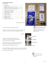
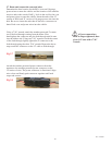
To adjust your antenna switch setting, remove the screws (16) that
attach the radome to the base. Carefully remove the radome and
set it down beside the unit. Find the Antenna Switch located on
top of the main control board and adjust the switch to the
appropriate setting for the mounting option and satellite receiver
(See Fig 3.6).
The position switches are numbered 1 through 8, left to right.
Each switch position has a value of 1 or 0.
To select the 1 value, flip the switch to the down position.
To select the 0 value, flip the switch to the up position.
(FACTORY PRESET)
Some Coach manufac-
turers may have changed these
settings during installation.
Verify mounting option and
receiver setting as shown.
Rev. 9/30/05


