


5
Assembly & Installation
Things you need —
Screwdrivers (Phillips and slot)
1-3/4” hole saw
7/16” wrench
ABS glue
Drill with 1/8” bit
Tape measure
Non-hardening sealant
(Check manufacturer’s specifications for
compatibility with your roof material.)
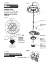
Winegard’s Digital Elevation Sensor has been
INSTALLED and CALIBRATED at the factory
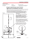
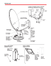
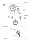
STEP 1. Choose a location on the roof for dish that will allow dish to raise and rotate without
interfering with other roof-mounted equipment. Make sure inside ceiling plate is easily acces-
sible, and with no obstructions that would interfere with operation.
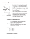
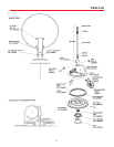
Figure 3 shows minimum distance (10”) antenna should be located from edge
of vehicle roof. It is recommended that you check with your dealer or manufacturer
for provisions that may have been made in the roof for antenna mounting; a
reinforced roof area or pre-wire installation
from the factory.
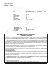
NOTE: The system must be level for
proper operation! Winegard Model
RW-5000 roof wedge with gasket is available. If
inside roof wedge is needed, Winegard’s
RW-2000 can be trimmed to fit ceiling plate.
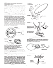
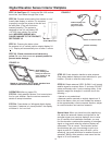
STEP 2. Position template on roof (see insert page of
this manual). CAUTION: DO NOT drill through
wiring. Carefully drill a 1-3/4” hole through roof and
ceiling of vehicle. Inspect hole to make sure wiring
is intact. (Roof template, see insert.)
It is highly recommended the antenna be
mounted on roof center line. Do not mount
antenna closer than 10” from roof edge.
NOT TO SCALE
RW-5000
Roof Wedge
with gasket
Vehicle Roof
Antenna Controls
Interior
Roof Wedge
(Optional)
Center Roof Line
MINIMUM
10”
17” RADIUS
29”
19.50”
34” DIAMETER
OPERATING
AREA
FRONT OF VEHCILE
FIGURE 3
Rev/7/9/04