


7
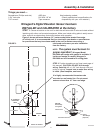
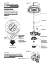
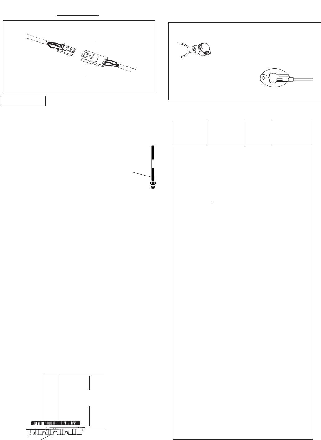
THREADED ROD,
WASHER
AND NUT
FIGURE 8
INSIDE RV
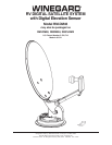
Special instructions: For roof thickness greater
than 6-1/2”.
Parts Needed: (not included)
RP-4400 14” worm gear for roof
3200369 Directional handle extension
2162031 Long threaded rod
Instructions:
STEP 8. Place nut on threaded rod.
See Figure 8.
STEP 9. Measure and cut the threaded rod with a
hacksaw. Use the chart in Figure 10 to determine the
correct length.
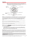
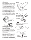
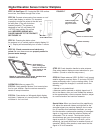
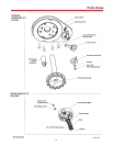
DIGITAL ELEVATION SENSOR ROOF CONNECTIONS
The illustrations below show the different methods of connecting wires at roof level; method will depend on
model. Wire colors MUST MATCH, ie. red to red, green to green, black to black.
This wire harness connects to the digital
elevation sensor on the antenna
NOTE: This terminal is NOT
WEATHERPROOF and CANNOT be left
outside on the roof.
Snap
connectors
together
Supplied with DM-2000 only
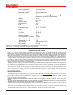
3M UR TERMINAL
NOTE: This terminal is weatherproof
and can be left outside on the roof IF
SECURED PROPERLY to prevent
wind whipping.
DO NOT STRIP
wires, terminal is
self-stripping.
Slide wires all the way in.
Squeeze pliers until
red plunger is flush
with res of terminal.
(Pliers not supplied.)
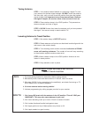
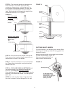
STEP 10. Remove the nut over the cut end of the
threaded rod. This cleans the threads after cutting.
STEP 11. Thread the cut end of the rod into the hub.
STEP 12. Install the ceiling plate. The rotate/lock le-
ver must point toward the rear of the vehicle.
Be sure rotate/lock lever is pointing towards the
rear of the vehicle and hole in ceiling plate aligns
with hole in the ceiling.
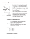
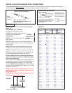
Refer to the chart to determine the correct length for
the directional handle. Extensions (3200369) may be
needed. Each extension adds 2-1/4” to directional
handle. DO NOT cut the extension, if the directional
handle must be extended by less than 2-1/4”, cut the
directional handle to fit.
NOTE: A tube cutter is recommended for cutting
the directional handle. This gives a square cut; a
hacksaw does not.
NOTE: Be sure large and small keyways line up in
the hub and directional handle!
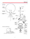
FIGURE 9
DIRECTIONAL HANDLE
Roof Directional Threaded Worm Gear
Thickness Handle Length Rod Length Shaft Length
(Figure 9) (Figure 11)
1-1/2" .................2-7/8" ................... 2-3/4" ................... 2-7/8"
1-3/4" .................3-1/4" ................... 3" ......................... 3-1/8"
2" ........................3-1/2" ................... 3-1/4" ................... 3-1/2"
2-1/4" .................3-7/8 .................... 3-1/2" ...................3-7/8"
2-1/2" .................4-1/8" ................... 3-3/4" ................... 4-1/8"
2-3/4" .................4-1/2" ................... 4" ......................... 4-1/2"
3" ........................4-3/4" ................... 4-1/4" ................... 4-3/4"
3-1/4" .................5" ......................... 4-5/8" ................... 4-7/8"
3-1/2" .................5-1/4" ................... 4-7/8" ................... 5-1/8"
3-3/4" .................5-5/8" ................... 5-1/4" ................... 5-1/2"
4" ........................5-3/4" ................... 5-1/2" ................... 5-3/4"
4-1/4" .................6-1/8" ................... 5-3/4" ................... 6-1/8"
4-1/2" .................6-1/2" ................... 6" ......................... 6-1/4"
4-3/4" .................6-5/8" ................... 6-1/8" ................... 6-3/8"
5" ........................6-7/8" ................... 6-3/8" ................... 6-5/8"
5-1/4" .................7-1/8" ................... 6-5/8" ................... 7"
5-1/2" .................7-3/8" ................... 6-7/8" ................... 7-1/4"
5-3/4" .................7-5/8" ................... 7-1/4" ................... 7-1/2"
6" ........................7-7/8" ................... 7-1/2" ................... 7-3/4"
6-1/4" .................8-1/8" ................... 7" ......................... 8"
6-1/2" .................8-1/2" ................... 7-3/4" ................... 8-1/4"
6 3/4".................. 8 3/4" ................... 8" ......................... 8 1/2"
7" ........................9" ......................... 8 1/4" ................... 8 7/8"
7-1/4" .................9-3/8" ................... 8 5/8" ...................9 1/8
7-1/2" .................9-5/8" ................... 8 7/8" ...................9 3/8
7-3/4" .................9-7/8" ................... 9 1/8" ...................9 5/8
8" ........................10-1/8" ................. 9 3/8" ...................10
8-1/4" .................10-3/8" ................. 9 5/8" ...................10 1/4
8-1/2" .................10-3/4" ................. 9 7/8" ...................10 3/8
8-3/4" .................11" ....................... 10" ....................... 10 5/8
9" ........................ 11-1/4".................. 10-1/4" ................. 11
9-1/4" ................. 11-1/2"..................10-5/8" ................. 11 1/4
9-1/2" ................. 11-3/4"..................10 7/8" ................. 11 1/2
9-3/4" ................. 12" ........................11 1/8" ................. 11 3/4
10" ...................... 12-3/8"..................11 3/8" ................. 12
10-1/4" ............... 12-5/8"..................11 5/8" ................. 12 1/4
10-1/2" ............... 12-7/8"..................11 7/8" ................. 12 1/2
FIGURE 10
HANDLE
LENGTH