


®
3
Remote Control Switchers
686-10
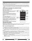
Power Interruption Status
The 686-10 should normally be plugged into an unswitched AC outlet. However, if the power to the 686-
10 is interrupted by a power failure or other reason, the internal memory will retain the last selected
switched status for each of the speaker relays.
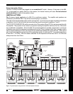
INSTALLATION
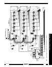
Fig. 3 shows a typical application of a 686-10 in a multiroom system. The amplifier and speakers are
connected to the Model 686-10 by the four-terminal plug-in connectors.
The order of the stereo speaker pairs used is not important. If you have only two pair of speakers connected
to positions 5 and 6, they will work just as well as they would connected to positions 1 and 2.
The PROTECTION RESISTOR switch connects a four-Ohm resistor IN and OUT of a series connection with
the amplifier. The purpose of the resistor is to prevent loading the amplifier with less than four Ohms with
any combination of speakers. Since the 686-10 connects speakers in parallel, anytime two or more pair
of speakers are active the impedance would be less than four Ohms (a typical "eight-Ohm" speaker usually
has an actual impedance of less than eight Ohms somewhere between 20 Hz and 20 kHz). When all six
pair of eight-ohm speakers are active and the protection resistor is switched OUT, the parallel impedance
is less than 1-1/3 Ohms. With the resistor switched IN, the impedance will be less than 5-1/3 Ohms but
always more than four Ohms.
1 2 3 4 5 6
ON
1 2 3 4 5
ON
PROTECTION
RESISTOR
OUT
IN
LEFT
LEFT GND
RIGHT GND
RIGHT
12 VDC
IR CONFIRM
AMPLIFIER
INPUT
L+
L-
R-
R+
+12V
GND
GND
IR IN
6
1
2
SPEAKER
3
54
REMOTE SPEAKER SWITCHER
686-10
OUT
+12V
IN
GND1
GND2
+12V
XANTECH
1 (ON)
0 (OFF)
1 2 3 4 5 6 7 8 910
ON
SENDER/
EMITTER
12345678910
794
UNIVERSAL INTERFACE
MAIN ROOM
480-00
Dinky Link ™
IR Receiver
S-62/64/66
Wall Speakers
3 Conductor Cables
for IR control signals
(Home Runs)
REMOTE ROOM 1
L
Speaker
Leads
(Home Runs)
780-10
"J" Box
IR Receiver
R
RCA patch
cords
RLRL
Cassette DecK
Left
Speaker
Right
Speaker
CD
Changer
R
760-00
Match Maker™
Vol. Control
760-00
Match Maker™
Vol. Control
760-00
Match Maker™
Vol. Control
480-00
Dinky Link ™
IR Receiver
490DW-00
"J" Box
IR Receiver
760-00
Match Maker™
Vol. Control
760-00
Match Maker™
Vol. Control
760-00
Match Maker™
Vol. Control
AV
Receiver
Center
Speaker
To 120 V AC
(u
nswitched)
782-00
Power
Supply
791-44
Amplified
Connecting
Block
686-10
Remote Speaker Switcher
Satellite Receiver
VCR
Laser Disc
SOURCE
COMPONENTS
Stereo Power Amp
L
RLRL RL
From Preout, Signal
Processor Out, etc.
794/797
Universal Interface
(Version depends on
brand of AV receiver)
(To Multiroom
input jack on
AV receiver)
REMOTE ROOM 2
REMOTE ROOM 3
REMOTE ROOM 4
REMOTE ROOM 5
REMOTE ROOM 6
Smart
Pad™
Smart
Pad™
282M or
283M
Mouse Emitters
+12 VDC
GND
EMITTERS
12 VDC
HIGH
IR
OUT
STATUS
IR IN
IR
RCVR
791-44
AMPLIFIED
CONNECTING BLOCK
R+ R- L- L+
Fig. 3 A Typical System using the 686-10 Remote Speaker Switcher