®
4
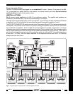
NOTE: When the 686-10 is connected to Xantech 760-00 Match Maker room volume controls, as shown
in Fig. 3, the PROTECTION RESISTOR is not necessary, since the Match Makers, when set correctly, will
provide the proper impedance match to the multiple speakers with virtually no power loss. In this case, be
sure the PROTECTION RESISTOR switch is set to the "OUT" position to prevent the waste of amplifier
power.
• • •
IMPORTANT
• • •
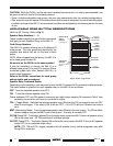
1. The Model 686-10 is intended to be mounted on a vertical surface so that the ventilation slots are at
the top and the bottom of the unit. Air should be allowed to circulate into the bottom slots and out of
the top slots, particularly when the PROTECTION RESISTOR is switched IN. The Model 686-10 will
mount onto a standard 19-inch rack.
2. Power Supply Considerations. Because of the high current requirement of the relays in the Model 686-
10, the Xantech Model 782 High Current Regulated Power Supply
must
be used. In Fig. 3, all of the
system IR control devices are also powered from the 782 through the 686-10.
To be sure you have sufficient power supply capability in your particular system, calculate the total
current required by using the method shown in the 791-44 instructions, then add 300 mA for the
686-10. If the total exceeds 1A, use a second supply to power the IR devices separately through the
791-44.
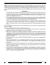
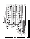
When the installation requires more than six sets of speaker pairs, two or more 686-10's may be connected
as shown in Fig. 4.
When using multiple 686-10's, keep the following items in mind:
1. Follow the instructions that come with the 760-00 Match Maker volume controls to ensure proper
impedance matching of all the speakers to the power amplifier.
2. Fig. 4 drives 18 stereo pairs, reflecting an impedance of 3.56 Ohms to the power amplifier (assuming
all speakers are 8 Ohms each and the 760's are all set to the 8X position). This is satisfactory provided
the amplifier you are using is safe into 3.56 Ohms. If not, you may need to switch the PROTECTION
RESISTOR to the IN position on one or more of the 686-10's, or use additional amplifier(s) to drive the
686-10's individually.
3. Remember, when you switch a PROTECTION RESISTOR IN, the volume level to the speakers will
be decreased.
4. When using multiple 686-10's or in combination with a 680-10 or other devices that respond to RC68+
codes, be sure each is set to a different IR CODE GROUP. Refer to Fig. 2 and the RC68+ Programmer
Instructions.
5. To perform Group ON and OFF with multiple 686-10's, it is necessary to sequence (macro) the different
ON and OFF codes for each 686-10 in a learning device, such as the Xantech URC-1 Remote, a Smart
Pad™, or a 590-00 Controller.
6. A CB18 Strip-IR Connecting Block is used in Fig. 4 to make the parallel connections from the IR
devices to the 791-44 Connecting Block. In this example, only 8 IR devices are shown connected to
the CB18. You would actually have to "double-up" on each of these connections if you need IR control
from all 18 rooms, or use an additional CB18.
686-10