


4
RC68+
CODE GROUP SETTING PROCEDURES
Use these procedures to:
a) Select the Code Group Number on the RC68+ to match the Code Group Number internally preset
at the factory for the specific Xantech model you wish to control.
b) Change the Internal Code Group Number of a Xantech model. You would do this to avoid mutual
interaction when using two or more of the same model on the same IR network (bus).
Setting the RC68+ Code Group Number
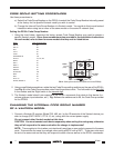
1. Using the chart below, determine the factory preset Code Group Number you need to operate a
specific Xantech model.
Since these numbers are also provided in the Installation Instructions
for each model, refer to them for newer models that may not be listed below.
Model Code Group Number
680-10 88
686-10 98
AC2 28
CC12 50
CC62 60
GATEKEEP-IR C8
IR-DC4 D1, D2, D3
MIRV1 30
RAT1 30
RGC11 30
RP41AV 40
RS41AV 20
SmartPad3 D8
SR21 50
RT8 58
RT16-10 70
ZPR68, ZPR68-10 68
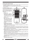
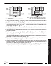
2. Using a small blade screwdriver, rotate the two Code Group setting switches on the rear of the RC68+
(see Fig. 4) to the Code Group number noted from the previous chart. The Left switch is the first digit
in the number and the Right switch is the second digit.
3. The Xantech model should now respond to the RC68+ commands that relate to that device (i.e.,
volume up/down, input selection, etc.). Fig. 4 shows the switches set to 68, the Code Group number
for the ZPR68.
CHANGING THE INTERNAL CODE GROUP NUMBER
OF A XANTECH MODEL
1. Connect a Xantech IR receiver (Model 780, 480, etc.) to the IR terminals of the Xantech device you
wish to change (RAT1/MIRV1, RT16-10, etc.) along with the correct power supply.
Do not connect other Xantech models at this time.
CAUTION:
You must connect each device separately when setting the code group, otherwise
they will all respond to the same code after the change is implemented!
NOTE: The exception to this is when you intentionally want two or more units to respond to the same
code. This would be the case, for example, when using a MIRV1 with a RAT1. These two units must
be set to the same code so that they will respond to each other as well as to the RC68+ commands.
FIG. 4 Setting the code switches (68 shown for the ZPR68)
1st Digit
(Left)
2nd Digit
(Right)
RC68+
(rear
panel)
0
1
2
3
4
5
6
7
8
9
A
B
C
D
E
F
0
1
2
3
4
5
6
7
8
9
A
B
C
D
E
F
0
1
2
3
4
5
6
7
8
9
A
B
C
D
E
F
0
1
2
3
4
5
6
7
8
9
A
B
C
D
E
F
CODE GROUP