5
Amplifiers & Preamplifiers
RC68+
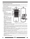
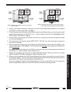
2. Using a small blade screwdriver, rotate each of the two Code Group Setting Switches on the rear of
the RC68+ to the F position (FF). See Fig. 5.
3. Turn the remote over and locate a Code Group number that is different than any other Xantech model
used in the same system (i.e., 48, D0, C0, etc.). These numbers are printed on the front face of each
RC68+ button! (See item #17, Fig. 3).
4. Aim the RC68+ at the Xantech IR receiver (780, 480, etc.) and press the button that has the number
on it that you decided on.
5. The control chip in the Xantech device (MIRV1/RAT1, RS41AV, etc.) will now change to respond to
the code you selected.
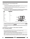
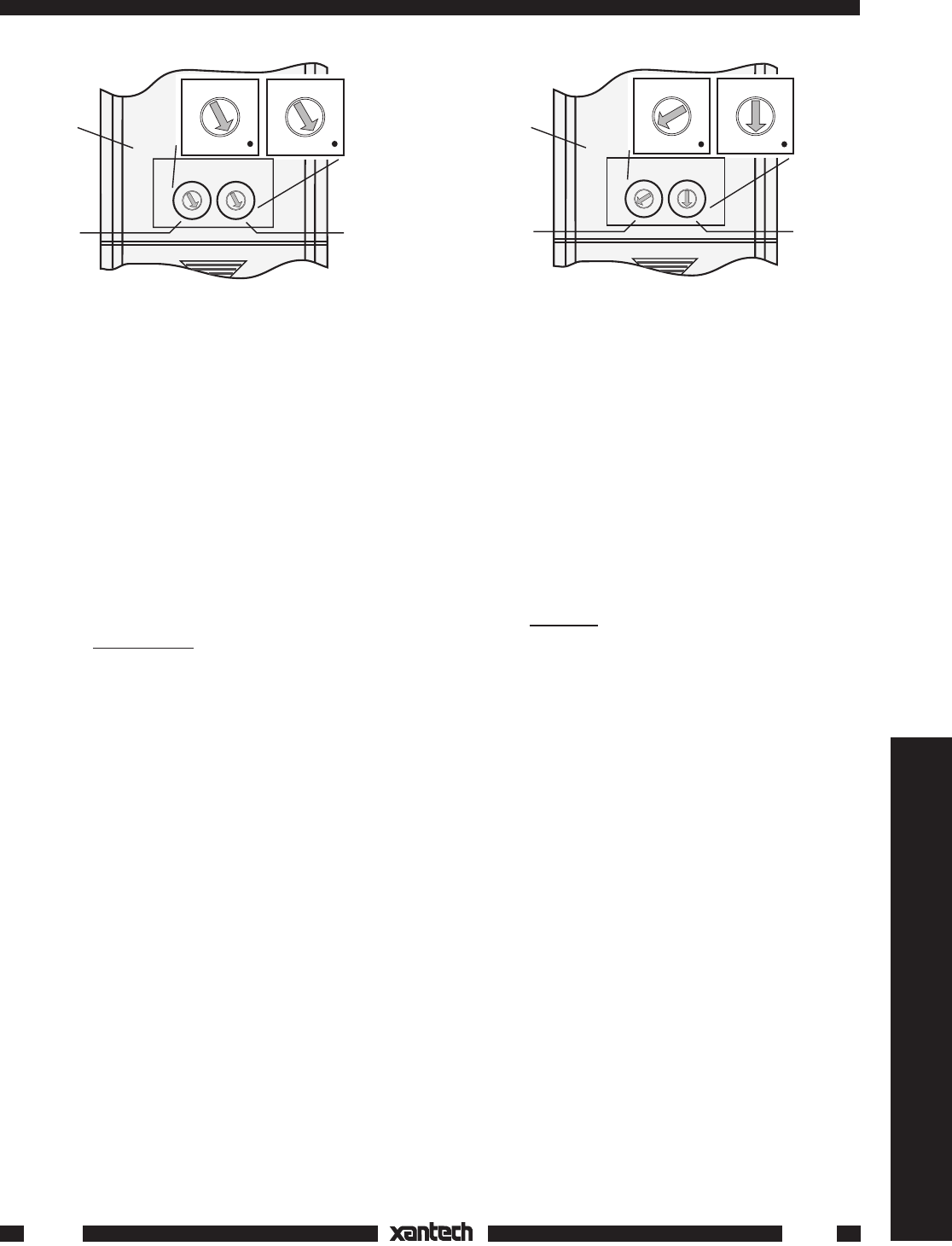
6. Test the system by rotating each of the Code Group Setting Switches on the rear of the RC68+ to the
chosen code number (refer to Fig. 6). The Left switch is the
first digit in the number and the Right one
is the second digit.
The device should now respond to the RC68+ commands that relate to the operational functions of
that device (i.e., volume up/down, input selection, etc.).
7. Repeat this procedure, as necessary, for each duplicated Xantech device you have in the same
system (except the ZPR68), changing the Code Group each time.
8. When you have completed the Code Group settings for each device, you may then connect them into
the same IR network. You will now need to "teach" these commands into learning devices such as
the Xantech URC series Learning Remotes, SmartPads, etc.
Be sure to change the Code Group Setting Switches on the rear of the RC68+ (Fig. 6) to match the
newly changed code number you set for each device, during the teaching process.
1st Digit
(Left)
2nd Digit
(Right)
RC68+
(rear
panel)
0
1
2
3
4
5
6
7
8
9
A
B
C
D
E
F
0
1
2
3
4
5
6
7
8
9
A
B
C
D
E
F
0
1
2
3
4
5
6
7
8
9
A
B
C
D
E
F
0
1
2
3
4
5
6
7
8
9
A
B
C
D
E
F
CODE GROUP
FIG. 5 Switches set to FF for Code Group changes.
Refer to step 2.
1st Digit
(Left)
2nd Digit
(Right)
RC68+
(rear
panel)
CODE GROUP
0
1
2
3
4
5
6
7
8
9
A
B
C
D
E
F
0
1
2
3
4
5
6
7
8
9
A
B
C
D
E
F
0
1
2
3
4
5
6
7
8
9
A
B
C
D
E
F
0
1
2
3
4
5
6
7
8
9
A
B
C
D
E
F
FIG. 6 Setting the code switches to the newly changed
code. Refer to step 6. (30 shown for MIRV1/RAT1).
8-28-00