


References
Other Functions
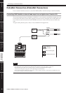
Connecting to an
External Device
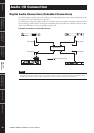
Audio I/O
Connection
Connecting to
a Computer
Controls and
Connectors
Introduction to
the DME Satellite
Foreword
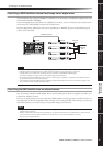
Connecting to a Computer
DME8i-C/DME8o-C/DME4io-C Owner’s Manual
25
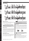
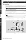
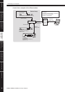
Control from a computer in the same subnet group
NOTE
• The IP addresses in the diagram are examples.
•Use a switching hub that is compatible with 100Base-TX/10Base-T network speeds.
The maximum length of a cable between a switching hub and the DME Satellite is 100 meters. Due to the quality of cables
and switching hub performance, however, proper operation at the maximum length cannot be guaranteed in some cases.
Use a STP (Shielded Twisted Pair) cable to prevent electromagnetic interference.
•If you are using multiple DME series units, set Link Mode on each unit to the same setting. Yamaha recommends that you
select 100Base-TX for the Link Mode setting.
•You can also connect a supported controller such as the AMX or Crestron, and control the DME Satellite remotely. For
details, refer to “Connecting to an External Device” on page 30.
HOMEHOME UTILITYUTILITYSCENESCENE LEVELLEVEL MUTEMUTE
ENTERENTERCANCELCANCEL
USB
PEAK
PEAK
SIGNAL
SIGNAL
PEAK
PEAK
SIGNAL
SIGNAL
PEAK
PEAK
SIGNAL
SIGNAL
INPUT
INPUT
DIGITAL MIXING ENGINE SATELLITE
USB
PEAK
PEAK
SIGNAL
SIGNAL
PEAK
PEAK
SIGNAL
SIGNAL
PEAK
PEAK
SIGNAL
SIGNAL
INPUT
INPUT
DIGITAL MIXING ENGINE SATELLITE
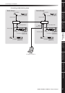
Device Group
Group Master
DME Satellite (IP address: 192.168.0.7)
Ethernet Cable
Switching Hub
Ethernet Straight Cable
Computer
(IP address:
192.168.0.100)
Ethernet Cable
Ethernet
Straight Cable
DME Satellite
(IP address: 192.168.0.3)
(Master ID: 7)
DME64N/24N
(IP address: 192.168.0.250)
(Master ID: 7)