194
CHAPTER 10 UART
10.1 Overview of UART
The UART is a general-purpose data communication interface. The UART supports both
synchronous clock and asynchronous clock mode and transmits variable-length serial
data. The transmission format is the "NRZ" system and the transmission data rate is
configurable by setting the proprietary baud rate generator, external clocks, internal
timers.
■ UART function
The UART communicates with other CPU’s and peripheral devices by transmitting/receiving serial data
(serial input/output).
• The full-duplex double buffer embedded in the device enables full-duplex bi-directional
communication.
• User can configure the UART to the synchronous transfer mode or asynchronous transfer mode.
• Internal baud rate generator allows user to select a baud rate from eight different speed (for internal
clock). The baud rate is also configured by setting external clock inputs and 8-bit PWM timer, allowing
flexible setting of rate.
• The variable data length system allows users to set the data length at 5, 8 and 9 bit with non-parity or 4,
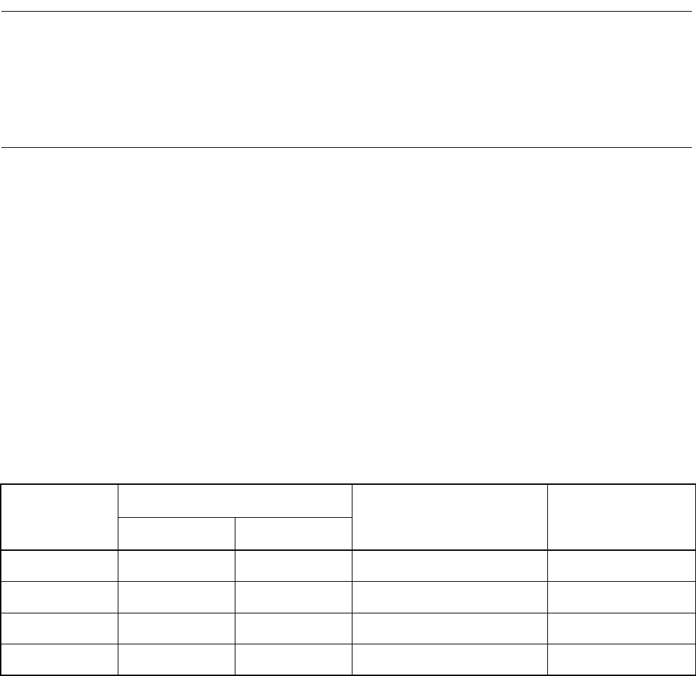
7 and 8 bit with parity (See Table 10.1-1 "UART operating mode").
• The data transmission format is based on the NRZ (Non Return to Zero) system.
Table 10.1-1 UART operating mode
Operating mode
Data length
Clock mode Stop bit length
Non-parity Parity
0 5 4 Asynchronous/Synchronous
1 bit or 2 bits
(*1)
1 8 7 Asynchronous/Synchronous
1 bit or 2 bits
(*1)
2 8+1 -- Asynchronous/Synchronous
1 bit or 2 bits
(*1)
3 9 8 Asynchronous/Synchronous
1 bit or 2 bits
(*1)
*1: In the receive mode, only the stop bit of length 1 is valid and the second bit received is always ignored.


